
 USD
USD


Filter

Format
Featured
Price
Tags
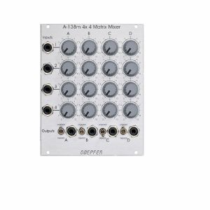
By means of an internal jumper one can select if the four upper controls work as DC offset generators - provided that no patch cord is plugged into the upper input socket. If this feature is not required it can be deactivated by removing the jumper on top left of the pc board. The function is identical to the A-138a/b.
Dimensions
20 HP
20 mm deep
Current Draw
30 mA +12V
30 mA -12V
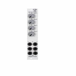
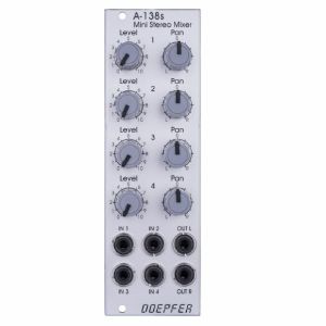
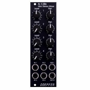
The module is the slim version of module A-138a and offers nearly the same features. But the distances between the controls are smaller and rubberized small-sized knobs are used. In return the front panel has 4 HP only which is half the width of the A-138a. The module is primarily planned for applications where only limited space is available. The only functional difference compared to the A-138a is the missing attenuator for the (dual) output.
Width: 4HP / 20.0 mm
Depth: 30 mm (measured from the rear side of the front panel)
Current: +10mA (+12V) / -10mA (-12V)
2 in stock $61.33
You may regard the A-138s as a smaller version of the A-138m Matrix Mixer.
Inputs and outputs are DC coupled, i.e. the module can be used for the mixing of control signals too.
- 3U Eurorack module, 8 HP wide, 30 mm in depth
- Power consumption: 10 mA at +12 V and 10 mA at -12 V
quote 671589
You may regard the A-138s as a smaller version of the A-138m Matrix Mixer.
Inputs and outputs are DC coupled, i.e. the module can be used for the mixing of control signals too.
- 3U Eurorack module, 8 HP wide, 30 mm in depth
- Power consumption: 10 mA at +12 V and 10 mA at -12 V
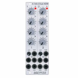
Each ADSR provides these controls and in/outputs:
- LED (displays the envelope output)
- A: manual Attack control
- D: manual Decay control
- S: manual Sustain control
- R: manual Release control
- Gate Input
- Retrigger Input
- CVT Input with attenuator (CVT = CV Time)
- Envelope Output 1
- Envelope Output 2
The output voltage range for each envelope is 0 - 10V. The time range of Attack/Decay/Release is about 1ms to 30s.
By means of internal jumpers one can select which time parameters are controlled by the CVT input (e.g. D only or D+R or A+D+R) and in which direction (i.e. if an increasing CVT shortens or stretches the time parameter in question).
Socket CVT can be normalled to an internal fixed voltage (i.e. the switching contact is connected to an internal fixed voltage). That way it's possible to change all time parameters simultaneously by means of the CVT control.
Another jumper is used to set output 2 to normal or inverted envelope.
And another jumper is used for the normalling of Gate 2 to Gate 1 (i.e. ADSR#2 is also triggered by Gate 1).
Two more jumpers are used for the optional bus access to the gate signal of the bus for each ADSR. Changing the positions of the mentioned jumpers allows to modify the factory settings.
1 in stock $149.51
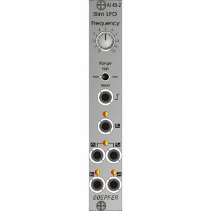
Five waveforms are available: sawtooth, inverted sawtooth, triangle, sine and square wave. The LFO can be used as a modulation source for any number of modules - for instance modulating the pulse width or frequency of a VCO, modulation of the cut-off frequency of a VCF, or amplitude modulation with a VCA.
A three-way switch lets you select three frequency ranges, spanning from one cycle every several minutes at the lowest, to moderate audio frequency at the highest (about 4-5 kHz).
The LFO signal can also be synchronised, via the reset input.
Identical to the A-145-1, but only 4 HP wide and with additional LEDs for the square wave and the sawtooth signal.
Power consumption: 30mA at +12V and 20mA at -12V
Depth: 45mm
4 HP
This product is available for pre-order at Juno, for shipping on the release date. You won’t be charged until the order is despatched.
We'll keep you informed of your order at every stage, and let you know if the release date changes.
If the price of the item drops before it's released, you will pay the lower price, but if it increases, you'll only pay the price you see today.
If you also include in-stock items on your order, they’ll be charged and shipped within 24 hours as usual.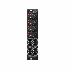
The module can be treated as a slimmed version of the quad LFO A-143-3 as it has similar features available. But the distances between the controls are smaller and rubberized small-sized knobs are used. In return the front panel has 4 HP only which is less than one third of the A-143-3. The module is primarily planned for applications where only limited space is available. The functional difference compared to the A-143-3 are the missing sawtooth outputs and frequency range switches.
quote 760210
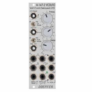
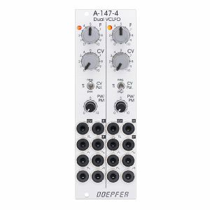
- VCLFO: voltage controlled low frequency oscillator
- VCA: voltage controlled amplifier, switchable to voltage controlled polarizer
- VC delay unit: voltage controlled linear attack envelope (only one parameter: attack) for delayed LFO operation in combination with the VCA (e.g. delayed vibrato/tremolo)
LFO: The voltage controlled LFO has the waveforms Triangle, Sine, Sawtooth and Rectangle available and features a Reset/Sync input. Triangle/Sine and Rectangle are displayed by means of dual-colour LEDs (probably red/green), Sawtooth has a unicolor LED available (probably blue). The output levels are about -4V...+4V for Triangle, Sine and Rectangle. The Sawtooth level is about 0...+8V.
The CV control can be switched to attenuator or polarizer ("CV Mode" switch). In polarizer mode the CV inputs affects the frequency in the reverse manner when the CV control is left from the centre position. In the centre position CV has no effect and right from the centre the control works like a normal attenuator. The frequency range (without external CV) is from about 0,005 Hz (i.e. about 3 minutes per period) to 200 Hz (with external CV max. frequency about 1kHz). In addition a ultra-low mode can be activated by means of an internal jumper. When the ultra-low jumper is set a fixed voltage is connected to the switching contact of the "LFO CV" socket. In polarizer mode of the CV control that way extremely low frequencies (up to one hour period and more) are possible. For this a jumper has to be installed on the pin header JP6. In the factory a dummy jumper is installed on the pin header JP7 "Dummy". JP7 has no function and is used only for "parking" of the jumper. Simply remove the jumper from JP7 and plug it on JP6. JP6 is located behind the CV control.
VCA: This is a linear VCA that can be switched to "normal" VCA (i.e. kind of a voltage controlled attenuator) or voltage controlled polarizer ("VCA Mode" switch). In the "normal" VCA mode amplification +1 is achieved with about +5V control voltage. In polarizer mode the amplification ranges from about -0.5 (i.e. inverted signal with about 50% level) with 0V CV to +0.5 (i.e. non-inverted signal with about 50% level) with +5V CV. With about +2.5V CV the signal is suppressed. Details about the functioning of a voltage controlled polarizer can be found in the description of the module A-133. In this mode the VCA can be treated also a DC coupled ring modulator (similar to A-114).
The VCA of the A-147-2 has three sockets available: "In" (signal input), "Out" (signal output) and "CV" (control voltage input).
The Triangle Output of the LFO is normalled to the VCA signal input by means of the switching contact of the "VCA In" socket. If another LFO waveform (or any other signal) should be processed by the VCA the corresponding signal has to be patched to the "VCA In" socket. The VCA can be used also independently from the LFO and the Delay CV. In this case the VCA sockets In, Out and CV have to be patched accordingly. The VCA can be used also as waveshaper for the LFO signals (e.g. by patching VCA In and VCA CV to different LFO signals, if necessary via attenuator A-183-1 or offset generator/attenuator A-183-2).
Attack/Delay: The third sub-unit of the module is a simple, voltage controlled envelope generator that has only the parameter "Delay" (or Attack) available. This unit generates a linear increasing voltage that starts from 0V after each Delay Reset until it reaches about +5V. Then the voltage remains at +5V until the next Delay Reset occurs. The inclination or gradient is controlled by the manual Delay control and the Delay control voltage ("Delay CV" input). The waveform is linear, the control scale is exponential. The output voltage is displayed by a green LED and available at the "Delay Out" socket.
The manual Delay control ranges - without external "Delay CV" - from about 5ms (fully CW) up to 2 minutes (fully CCW). By means of an external voltage applied to the "Delay CV" socket this range can be extended. A rising CV shortens the delay time (behaviour like a VCO)!
The Delay output voltage ranges from about 0V to +5V. The rising edge of the gate, clock or trigger signal applied to the "Delay Reset" sockets resets the Delay output voltage to 0 V.
"Delay Out" is normalled to the VCA CV input by means of the switching contact of the "VCA CV" socket and consequently controls the Triangle level provided that no other patch is made. A typical example is the usage of a Gate signal (e.g. from a USB/Midi-to-CV/Gate interface) as Delay Reset. That way a delayed vibrato or tremolo can be realized if the VCA output is patched to the frequency CV input of a VCO (or VCF), or the CV input of a VCA.
1 in stock $130.52
The module has these controls and in/outputs available:
Control F : manual control of the frequency, for each LFO the frequency range can be selected by means of a jumper from two values (see technical notes)
frequency coverage of control F in the high frequency range: about 0.075 Hz (~ 13 seconds) ... 1,4kHz
frequency coverage of control F in the low frequency range: about 0.007 Hz (~ 140 seconds) ... 125Hz
Control CV: attenuator for the signal applied to the CV socket, by means of a jumper a small positive voltage can be applied to the switching contact of the /CV/ socket, as long as no patch cable is connected to /CV/ socket the CV control then works as fine control for the frequency
Switch CV Pol.: polarity switch for the signal applied to the socket /CV/
Control PW/PM: combined control for manual and CV control of the rectangle pulsewidth:
when no patch cable is connected to socket /P/ the control is used to adjust the pulsewidth (PW) manually
when a patch cable is connected to socket /P/ the control works as attenuator for the external CV signal with a basic pulsewidth of 50:50.
Socket /CV/: frequency control voltage input, in the factory the module is adjusted so that the sensitivity of this input is exactly 1V/octave when the CV control is fully CW.
Socket /R/: reset input, according to the associated jumper the reset input is edge triggered or level controlled (see technical notes for details)
Socket /P/: pulsewidth control voltage input
Sockets with waveform symbol: output of the waveform in question (triangle, sine, rising and falling sawtooth, rectangle)
The output voltage ranges are about -5V ... +5V (10Vpp), except the rectangle output
For the rectangle output one can choose by means of a jumper if the range is about -5V ... +5V or 0...+10V.
LED: visual control of the LFO (triangle)
The inputs of the module are labelled with white characters on black background (in the text included into two slashes). The outputs are labelled with black characters.
Technical notes and special features:
The basic frequency range of each LFO can be selected by means of a jumper. The settings correspond to two different capacitor values for the VCO circuit. The relation between the two ranges is about 1:11. When the upper range is selected frequencies from about 0.02 Hz up to 2.5kHz can be generated. For the lower range the values are about 0.0017 Hz ... 220Hz. To obtain these full frequency ranges external control voltages are required. With the frequency control F only the frequencies mentioned above are possible.
Apart from that the range for the manual control F can be reduced to obtain a finer resolutuion. For this a jumper has to be removed. The range of control F is then reduced to about 1:4.5 only.
In the factory the starting voltage of the triangle output after a reset is adjusted to 0V, i.e. the triangle starts from 0V with the rising slope after a reset. By means of a trimming potentiometer the starting voltage can be adjusted to another value (e.g. to -5V).
Another jumper is used to set the reset behaviour to edge triggered or level controlled. When set to edge triggered the rising edge of reset signal is used for the reset (independent of the duration of the "high" state of the reset signal). When set to level controlled the triangle output remains at the starting voltage as long as the reset signal is "high". Only when the reset signal turns "low" the triangle starts.
Dimensions
8 HP
45 mm deep
Current Draw
80 mA +12V
70 mA -12V
1 in stock $195.09
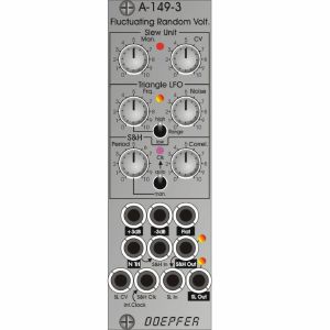
Module A-149-3 is based on the homonymous "Fluctuating Random Voltages" by Buchla. Compared to the historic original, a lot of functions have been added. For example the user has access to virtually all internal signals (e.g. Noisy Triangle or S&H) and there are a lot of adjustable parameters which were fixed in the original.
For example, the frequency and noisiness of the internal triangle oscillator, the correlation of the S&H and manual or automatic frequency control of the S&H clock oscillator. The fixed internal connections of the original are wired to sockets in the A-149-3 and can be used also individually as the connections of the original are realized as normalled sockets. That way e.g. the S&H or slew unit can be used independent from the other units.
The functions in detail:
As in the original a digital noise signal is filtered in three different ways. The three "noise flavours" are available at three sockets and can be used for all kind of noise applications:
+3db (+3dB per octave, a bright noise, also called blue noise)
-3dB (-3dB per octave, a dark noise, also called red or brown noise, Allan Strange calls it "reciprocal white noise")
Flat (flat spectrum, also called pink noise)
In the original the -3dB output is used add some noise to an internal triangle oscillator with fixed frequency (~ 100 Hz) and fixed "noisiness". The result is called "noisy triangle". In the A-149-3 the frequency of the triangle oscillator and the level of the noisiness can be adjusted. The frequency is adusted by means of the Frq. control and the Range switch (~ 110Hz ... 5 seconds period in position high). In addition one can select between the -3dB and Flat output as noisiness source by means of an internal jumper. When Noisiness control is fully CCW one obtains a clean undisturbed triangle signal. With Noisiness control fully CW the result is a triangle signal with a lot of noise or randomness. The noisy triangle signal is available at the socket "N Tri" and is displayed with a dual colour LED.
The "N Tri" signal is normalled to the signal input of the subsequent Sample&Hold unit (S&H). The clock signal for the S&H is generated by an internal rectangle oscillator. This signal is normalled to the S&H clock socket and is displayed by an LED. One can select between manual and automatic control of the clock period by means of a toggle switch. In position "man." the period is controlled manually by the "Period" control. With control "Period" fully CCW one obtains the shortest period or highest frequency. Turning the control up increases the period or lowers the frequency. In position "auto" of the switch the period is controlled by the slew unit.
In this position a vactrol is used to define the frequency of the S&H clock. This vactrol is controlled in the same way as the vactrols of the slew unit, i.e. the period of the S&H clock changes simultaneously with the slew time. In the historic original only the auto mode was available. There was no manual control available.
The S&H has another special feature: the Correllation control. It's a feedback function where shares of the S&H output are fed back to the S&H signal input and mixed with the actual S&H input signal. The result is slurring the signal like a sub-audio lowpass filter, kind of a "digital slew function" because the gradation of the signal persists.
The S&H output is availabe at the corresponding socket and is displayed with a dual colour LED.
The S&H output is normalled to the signal input of the subsequent Slew Limiter unit (SL). The core of the slew limiter are two vactrols (vactrol = combination of a light emitting diode/LED and a light dependent resistor/LDR built into lightproof case). The brightness of the vactrol LEDs can be controlled manually (control "Man." of the slew unit) and by an external control voltage (socket "SL CV" with associated attenuator "CV" of the slew unit). The brightness of the vactrol LEDs is displayed at the top of the front planel. As already mentioned a third vactrol can be used to control the frequency of the S&H clock oscillator simultaneously to the slew limiter. The SL output is availabe at the corresponding socket and is displayed with a dual colour LED.
Due to the access facilities to many of the internal signals and connections it's possible to use the sub-units also for other applications. E.g. the noisy triangle signal, the S&H unit (incl. correlation) or the SL unit can be used for other signals. The S&H clock can be applied also from outside to synchronize the S&H to other signals.
If required, the internal clock signal is available at a pin header of the pc board.
Controls, Switches and Displays:
Slew Unit
Man.: manual adjustment of the slew time
CV: attenuator for the SL CV input
LED: display of the slew function (bright = short slew lime, dark = long slew time), identical to the brightmess of the vactrol LEDs
Triangle LFO
Frq.: LFO frequency, range ~ 110 Hz ... 5 seconds period
Noise: adjustment of noisiness (= perturbance of the triangle signal)
+3dB/-3dB: switch for the source of noisiness
LED: display of the noisy triangle signal, dual color LED (rot = positive / yellow = negative output voltage)
Sample&Hold (S&H)
Period: period of the internal clock signal for the S&H unit, fully CCW = shortest period or highest frequency, fully CW = longest period or lowest frequency
LED: display of the internal clock signal
Correl.: adjustment of the correllation of the S&H unit
Man./Auto: switching between manual and automatic control of the clock frequency, when auto is selected the clock frequency is controlled by the slew unit
LED: display of S&H output, dual color LED (rot = positive / yellow = negative output voltage)
Slew Limiter (SL)
LED: display of SK output, dual color LED (rot = positive / yellow = negative output voltage)
Sockets:
+3dB : filtered digital noise with +3dB per octave (output)
-3dB : filtered digital noise with -3dB per octave (output)
Flat : flat noise output
N Tri : Noisy Triangle output, about 10Vpp (-5V ... +5V)
S&H In: S&H signal input, normalled to N Tri
S&H Out : S&H signal output
SL CV: control voltage of the slew limiter unit, connected to the corresponding attenuator "CV" of the slew unit
S&H Clk: clock input of the S&H unit, normalled to the internal clock oscillator
SL In: slew limiter input, normalled to S&H Out
SL Out : slew limiter output
The arrow symbols indicate the normalling of sockets. Outputs are inverse labelled.
Technical details:
Frequency range of the triangle LFO: about 110 Hz ... 5 seconds period
Output level of the triangle LFO: ~ 10 Vss (-5 V...+5 V)
Frequency range of the internal clock oscillator: about 3 seconds ... 30Hz
Output level of the internal clock oscillator: ~ 10 Vss (0 V...+10 V)
Required input level of the S&H clock input: +5V
Depth: 45mm
8 HP
This product is available for pre-order at Juno, for shipping on the release date. You won’t be charged until the order is despatched.
We'll keep you informed of your order at every stage, and let you know if the release date changes.
If the price of the item drops before it's released, you will pay the lower price, but if it increases, you'll only pay the price you see today.
If you also include in-stock items on your order, they’ll be charged and shipped within 24 hours as usual.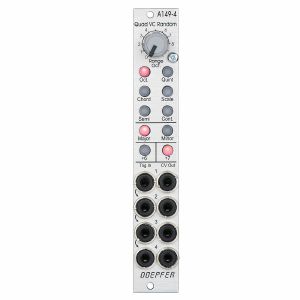
Manual controls for the criteria selection:
Octave range (manual control "Oct."): this parameter defines how many octaves are covered by the random voltages (0 ... +5V, with "Oct." control fully CCW only 0V are generated)
Grid (6 illuminated radio buttons): this parameter defines the grid of the random voltages:
Octaves (Oct)
Octaves + Quin (Quint)
Chords (Major or Minor chords)
Scale (Major or Minor scale)
Semitones
continuous (i.e. stepless)
Minor / Major (2 illuminated radio buttons): this parameter defines in case of chords or scales if they are minor or major. For all other grids this parameter has no meaning
Sixth / Seventh (2 illuminated separate buttons): these parameters defines if the sixth or seventh is added. Valid only if Oct, Quint, Chord or Scale is chosen as grid.
The output voltages follow the 1V/octave standard (i.e. 1/12 V voltage differenc per semitone) with exception of the Continuous mode. The voltages in this mode are totally random and do not follow the 1V/oct standard (i.e. not a multiple of 1/12V).
The generation of a new random voltage at the output (CV Out 1...4) is triggered by the rising edge of the signal applied to the corresponding trigger input (Trig. In 1...4). The trigger inputs are normalled top down. The minimum trigger level is +2.5V, the maximum level is +12V.
Applications:
random polyphonic structures (in combination with the polyphonic modules A-111-4, A-105-4, A-132-8, A-141-4 and e.g. A-157 as trigger source and A-173-1/2 for transposition of the polyphonic structures)
any application that requires several random voltages
four digital pseudo noise signals when higher trigger frequencies are used
Width: 4 HP / 20.0 mm
Depth: 50 mm (measured from the rear side of the front panel)
Current: +50A (+12V) / -10mA (-12V)
1 in stock $157.61
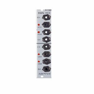
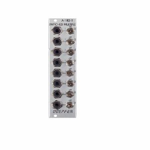
Each switch has a control voltage input, a common Out / Input, and two In / Outputs. The switches are bi-directional: they can work in both directions, so can connect one input to either of two outputs, or either of two inputs to one output. Voltages in the range -8V...+8V at the O/I resp. I/O sockets can be processed by the module.
Two LEDs show which in / output is active (i.e. which is connected to the common out / input).
quote 745778
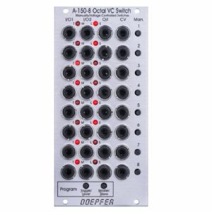
For each unit the operating mode can be selected: Toggle or Level controlled. In Toggle mode the rising edge of the CV input or operating the manual control button changes the state of the switch. In Level mode the switch state is defined by the voltage applied to the CV input (low voltage = I/O1, high voltage = I/O2) or by the state of the manual control button (not pressed = I/O1, pressed = I/O2). The modes are programmed very easily: Operating the Toggle/Level button of the program section displays the current state of each switch with the LEDs: left LED on = Toggle mode, right LED on = Level mode. Operating the manual control button of the switch in question changes the toggle/level mode while the Toggle/Level button of the program section is operated. During the programming patched CV signals may have to be removed as the CV signals would interfere with the manual operating buttons during the programming process.
In addition, it's possible to define master/slave groups. In such a group the upper unit (= master) controls also the state of the following switches provided that they are defined as slaves. Master/slave programming is also very simple: Operating the Master/Slave button of the program section displays the current state of each switch with the LEDs: left LED on = Master, right LED on = Slave.
When all 8 units are defined as master all switches are independent from each other. If for example the sequence is MSSSMSMS the control unit of the first switch also controls the switches 2, 3 and 4. The control unit of switch 5 also controls the switch 6, and the control unit of switch 7 also controls the switch 8. The current states of the slave switches are overwritten by the state of the master switch.
Technical note: To protect the electronic switches in case of an unsuitable patch (e.g. connection of two outputs) a 1k protection resistor is inserted into the O/I line of each switch. If control voltages used for VCOs are switched this may cause a small voltage drop and lead to undesired audible detuning. For this application we recommend to insert a CV buffer between A-150-8 and the VCO(s), e.g. the Buffered Multiple A-180-3 or the Precision Adder A-185-2. Integrating the buffers into the module A-150-8 was not possible because this would ruin the bidirectionality of the switches.
Width: 12 HP / 60.6 mm
Depth: 55 mm (measured from the rear side of the front panel)
Current: +40mA (+12V) / -5mA (-12V)
1 in stock $170.88
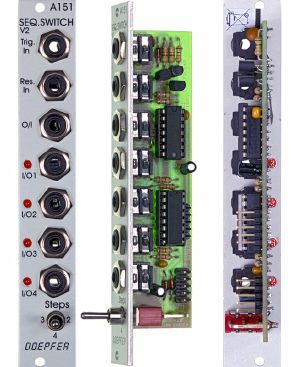
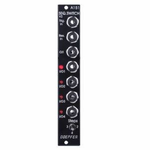
It includes trigger and reset inputs, four in / outputs, and a common out / input. Each time a pulse is received at the trigger input socket, the common out / input is connected to the next in / output. After the fourth in / output, the next trigger makes it step back to the first again, and so on. A positive pulse at the reset input switches the out / input immediately back to the first in / output.
Voltages in the range -12V...+12V at the O/I resp. I/O sockets can be processed by the module (not only control voltages but also gate, trigger or clock signals provided that they are in the -12V...+12V range).
By means of a toggle switch the number of steps can be limited to 2, 3 or 4.
Four LEDs indicate the active in / output (ie. the on that is connected to the out / input at any particular time).
For more detailed information please look at the English user's manual: A151_man.pdf.
Similar modules:
A-150-1 Dual Voltage Controlled Switch
A-150-8 Octal Manual/Voltage Controlled Programmable Switches
A-152 Voltage Addressed Track&Hold / Switch (Multiplexer) / Digital Outputs
Technical notes:
To protect the electronic switches in case of an unsuitable patch (e.g. connection of two outputs) a 1k protection resistor is inserted into the O/I line. If control voltages used for VCOs are switched this may cause a small voltage drop and lead to undesired audible detuning. For this application we recommend to insert a CV buffer between A-151 and the VCO(s), e.g. the modules A-180-3, A-180-4 or the Precision Adder A-185-2. Integrating the buffer into the module A-151 is not possible because this would ruin the bidirectionality of the switches.
For modules manufactured before spring 2005 the voltage range at the in/outputs was limited to -8V...+8V. From spring 2005 the revised version of the module was available. With an additional switch the number of steps can be set to 2, 3 or 4 (thanks to Peter Grenader for this idea). Moreover the revised module allows to process voltages in the full A-100 voltage range (i.e. -12V...+12V). The limitation to -8V...+8V is no longer valid. The A-100 DIY page describes how to install this additional switch for the old version of A-151.
Width: 4 HP / 20.0 mm
Depth: 35 mm (measured from the rear side of the front panel)
Current: +20mA (+12V) / -10mA (-12V)
It includes trigger and reset inputs, four in/outputs, and a common out/input. Each time a pulse is received at the trigger input socket, the common out/input is connected to the next in/output. After the fourth in/output, the next trigger makes it step back to the first again, and so on. A positive pulse at the reset input switches the out/input immediately back to the first in/output. Voltages in the range -8V...+8V at the O/I resp. I/O sockets can be processed by the module.
Four LED's indicate the active in/output (ie. the one that is connected to the out/input at any particular time).
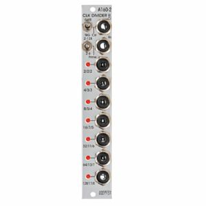
The A-160-2 also has a reset input. Whenever a reset signal is sensed, all outputs are set to certain levels which depend upon the selected mode.
These are the most important features of the module:
Three different sets of dividing factors, selected by a three-position switch at the front panel:
- Power of two: 2, 4, 8, 16, 32, 64, 128
- Prime numbers: 2, 3, 5, 7, 11, 13, 17
- Integer: 2, 3, 4, 5, 6, 7, 8
Two output modes, selected by a two-position switch at the front panel:
- Gate mode: outputs act like the outputs of typical binary dividers
- Trigger mode: in this mode the outputs are AND-wired with the clock signal (i.e. the clock pulsewidth affects the pulsewidth of the outputs)
- Clock edge type selected by a jumper on the pc board:
- Positive: the rising edge of the clock signal triggers the state change of the outputs
- Negative: the falling edge of the clock signal triggers the state change of the outputs
Reset behaviour by two jumpers on the pc board:
- Level triggered: the level at the Reset input triggers the Reset
- Edge triggered: the edge of the signal at the Reset input triggers the Reset
- Positive: a high level (> 2.5V) or the rising edge at the Reset input triggers the Reset
- Negative: a low level (< 1 V) or the falling edge at the Reset input triggers the Reset
Output polarity selected by a jumper on the pc board:
- Positive: non-inverted outputs
- Negative: all seven outputs are inverted
Width: 4HP / 20mm
Depth: 35mm (Measured from the rear side of the front panel)
Current: +12V: +50mA, -12V: -0mA
quote 671576
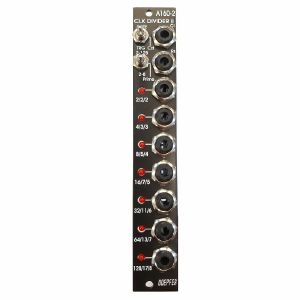
The Clock input will take any digital signal from, eg., an LFO, MIDI sync, or the gate from a MIDI-CV interface. At the outputs, you have access to three sets of seven different sub-divided clock signals, from half the clock frequency down to 1/128. The low/high levels of the output signals are 0V and about +10V.
The A-160-2V also has a reset input. Whenever a reset signal is sensed, all outputs are set to certain levels which depend upon the selected mode.
HP : 4
quote 864696
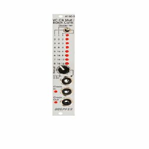
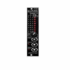
A manual control is used to adjust the clock multiplication factor manually without the need of an external control voltage. The voltage generated by this control ("Manual") is normalled to the CV In socket. As long as no plug is inserted into the CV In socket the clock multiplication factor is adjusted by means of the manual control knob and displayed by the LEDs. For dynamic applications (like the ratcheting function described below) the manually generated CV is overwritten by the external CV which has to be fed into the CV In socket.
The module can be used for all kind of clock multiplying applications. One important example is the generation of so-called ratcheting sequences. The band Tangerine Dream is famous for this kind of sequences. A normal sequencer generates only one gate signal per step. A ratcheting sequence may have also more than one gate pulses per step. This function can be obtained by using the A-160-5: one CV output of the sequencer is used to define the number of gate pulses per step. If the control of the step in question is fully CCW the generated CV is 0V and no gate signal is generated (mute of the step). When the control of the step in question is turned clockwise one, two or more gate pulses are generated depending upon the position of the mode switch and the voltage generated by the CV at this step.
Technical note: Due to the nature of clock multiplying it takes a few input clock pulses until the clock output is stable. One has to average a few input clock pulses to generate the multiplied clock output signal. Even when the input clock frequency changes it will take a few cycles until the output clock signal is correct as the module cannot foresee the future of the clock input signal. The generated clock output signal is derived from the last few cycles of the clock input signal. Consequently the module should be driven only by a clock signal with constant or slowly changing frequency.
quote 745787
A manual control is used to adjust the clock multiplication factor manually without the need of an external control voltage. The voltage generated by this control ("Manual") is normalled to the CV In socket. As long as no plug is inserted into the CV In socket the clock multiplication factor is adjusted by means of the manual control knob and displayed by the LEDs. For dynamic applications (like the ratcheting function described below) the manually generated CV is overwritten by the external CV which has to be fed into the CV In socket.
The module can be used for all kind of clock multiplying applications. One important example is the generation of so-called ratcheting sequences. The band Tangerine Dream is famous for this kind of sequences. A normal sequencer generates only one gate signal per step. A ratcheting sequence may have also more than one gate pulses per step. This function can be obtained by using the A-160-5: one CV output of the sequencer is used to define the number of gate pulses per step. If the control of the step in question is fully CCW the generated CV is 0V and no gate signal is generated (mute of the step). When the control of the step in question is turned clockwise one, two or more gate pulses are generated depending upon the position of the mode switch and the voltage generated by the CV at this step.
Technical note: Due to the nature of clock multiplying it takes a few input clock pulses until the clock output is stable. One has to average a few input clock pulses to generate the multiplied clock output signal. Even when the input clock frequency changes it will take a few cycles until the output clock signal is correct as the module cannot foresee the future of the clock input signal. The generated clock output signal is derived from the last few cycles of the clock input signal. Consequently the module should be driven only by a clock signal with constant or slowly changing frequency.
quote 745789
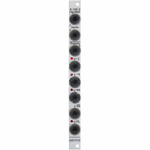
inverted signal of Input 1 (labelled 1)
inverted signal of Input 2 (labelled 2)
T flipflop (toggle flipflop), controlled by Input 1, this output changes it's state whenever a the rising edge of Input 1 appears (labelled 1/2, as it works similar to a 1:2 frequency divider)
Set/Reset flipflop, this output changes it's state to "high" during the rising edge of Input 1 and turns "low" during the rising edge of Input 2 (labelled RS)
inverted output of the Set/Reset flipflop (labelled RS)
pulse output, during both the rising and falling edge of Input 1 a short trigger pulse with about 50 ms lenght is generated (labelled with the sign ± and a rectangle pulse symbol)
The outputs 2, 1/2, RS and the pulse output are equipped with LEDs that display the state of the output in question.
The output level for all six outputs can be set to 0/+5V or 0/+11V by means of a jumper on the pc board.
Voltage thresholds for the input voltages:
voltages below +0,8 V are treated as "low"
voltages above +3 V are treated as "high"
Typical applications
starting and/or stopping of events or switching operations with the RS or RS output (e.g. controlled by the trigger outputs of a sequencer, e.g. in combination with electronic switches)
generation of inverted digital signals
frequency division (1/2 output)
generation of short pulses during the rising and falling edge of a digital signal (e.g. triggering an envelope at both rising and falling edge of a gate signal).
Technical notes
The module cannot be used for bipolar signals! The negative share of the input signal will be clipped by means of a so-called clipping diode at the input of module A-165-2. This may affect the output circuitry of the module connected to the A-165-2 (depends upon the details of the output circuit and if it is protected against clipping). For the planned field of application that's normally no limitation because these signals (clock, gate, trigger) work usually only with positive voltages.
The module can be used for analog signals only to a limited extend! With analog signals the inputs of the module work as comparators and the negative share of the input signal is clipped (as mentioned above).
Width: 2HP / 10.0 mm
Depth: ? mm (measured from the rear side of the front panel)
Current: +?mA (+12V) / -?mA (-12V)
quote 1021149
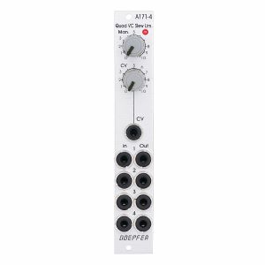
The common slew time can be adjusted manually and in addition controlled by an external control voltage. The module uses light-sensitive resistors (LDR). Therefore the slew times are not exactly the same for all units due to the tolerances of the LDRs and the LEDs, which are used to illuminate the LDRs. Inputs and outputs of the slew limiters are buffered to avoid voltage drops. This is especially important for polyphonic portamento applications. Each output can drive several VCOs without the need of external buffers. In addition the slew limiter inputs and outputs are available at internal pin headers for internal pre-wiring of polyphonic patches. As the switching contacts of the sockets are used for the internal pre-patching the internal patch can be overridden by using the sockets at the front panel.
The module has these controls and in/outputs available:
Control Man. : manual control of the slew limiter value (base value)
Control CV: attenuator for the signal applied to the CV socket
Socket CV: control voltage input
Sockets In 1...4: slew limiter inputs
Sockets Out 1...4: slew limiter outputs
LED: visual control of the slew limiter value (dark = long time, bright = short time)
Technical notes:
Each light-sensitive resistor (LDR) forms together with an associated capacitor a simple standard RC network (Resistor/Capacitor network). Input and output of each network are buffered.
The slew time range is about 5 ms ... 10 s (1:2000). Due to the tolerances of the LDRs and the LEDs the slew times vary a bit for each unit. By changing the capacitor values this range can be altered: by lowering the capacitor values the slew limiters can be used as 6dB low pass filters. Increasing the capacitor values result in longer slew times
The 4 photo resistors and LEDs are assembled within an small lighproof box. In addition the pc boards are made of lighproof black material to avoid interfering light from other modules or the bus board.
On the module pc boards two pin headers with 4 pins each are available. These are planned for the internal pre-patching of polyphonic modules:
In 1...4: The pins of this pin header are connected to the switching contacts of the sockets In 1...4. Hereby an internal four-wire connection to the CV outputs of the polyphonic midi-CV-interface A-190-5 can be made. As long as the sockets In 1...4 are not used the internal connection to the A-190-5 is established.
Out 1...4: The pins of this pin header are connected to the outputs Out 1...4. Hereby an internal four-wire connection to the CV inputs of the polyphonic VCO A-111-4 can be realized. If more than one VCO has to be controlled by one output we offer so-called micro multiples.
Dimensions
4 HP
45 mm deep
Current Draw
40 mA +12V
40 mA -12V
quote 945417
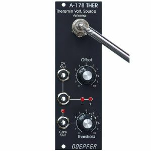
The distance range is about 30 cm. Additionally the module is equipped with a Gate output with adjustable threshold level. To simulate the original Theremin two A-178, a VCO (e.g. A-110) and a linear VCA (e.g. A-130 or A-132) are required. But of course the A-178 can be used to control other functions in the A-100 (e.g. filter frequency, modulation depth and/or speed, tempo, attack/decay time and so on).
The CV output voltage of the A-178 can range - according to the setting of the front panel controls - from -10V...+10V.
The gate output switches from 0V to about +10V.
Power consumption: 60mA at +12V and 20mA at -12V
Depth: 40mm
HP : 8
quote 852800
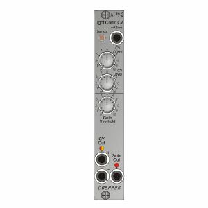
A light sensitive resistor (LDR) converts the illumination of the internal light sensor into a corresponding analog control voltage. The internal sensor is located at the front panel. Instead of the internal sensor a remote sensor can be connected via a standard patch cable to the module (ext.Sens. socket). An external sensor with a 2 m patch cable (A-100C200) is included. The external sensor is mounted on a small pc board which is equipped also with a 3.5 mm jack socket. The nut of the socket can also be used to mount the external sensor.
The module A-179 is similar to the Theremin module A-178 but uses the illumination intensity instead of the distance between hand and antenna for generating the analog voltage.
One can choose between passive control by covering/shading the sensor via hand or body, or active control by using e.g. a pocket lamp or flashlight. For this two versions of output voltages are available (CV Out + und CV Out -).
The module has these controls and in/outputs available:
ext. Sens.: by means of a standard patch cable the external sensor can be connected to this socket. In this case the internal sensor is turned off.
CV Offset: control to adjust the output voltage which is assigned to a certain illumination (e.g. 0V for complete darkness)
CV Level: control that is used to adjust the sensitivity of the generated output voltage (i.e. how much a certain difference in brightness affects the output voltage)
Gate Threshold: control that is used to adjust the threshold for the generation of the gate signal, an internal jumper is used to define if the gate signal is derived from the CV Out+ or CV Out- voltage.
CV Out+: positive control voltage output, increasing brighness causes the increase of the voltage at this output
CV Out+: negative control voltage output, increasing brighness causes the decrease of the voltage at this output
LED CV Out: bipolar LED (red/yellow) as display for the CV outputs
Gate: gate output with LED display
Applications:
controlling any voltage controlled parameter e.g. pitch or pulswidth of a VCO, filter frequency or resonance of a VCF, loudness of a VCA, time of an envelope generator, frequency of a VCLFO
triggering activities via gate with adjustable threshold, e.g. starting an envelope, starting/stopping a sequencer or any switching function (e.g. with A-150-1 or 151).
Conversion into MIDI control change messages is possible with the A-192-2.
Width: 4 HP / 20.0 mm
Depth: 30mm (measured from the rear side of the front panel)
1 in stock $71.82
Dimensions
2 HP
18 mm deep
Current Draw
Module does not draw current
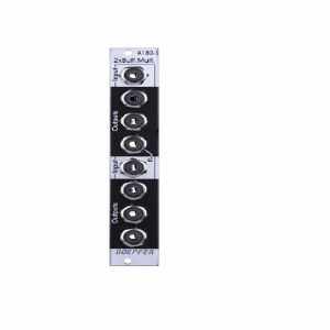
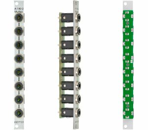
Application: copying/buffering of CV, gate and audio signals.
Examples:
- All switches in left position or all switches in right position: 8-fold multiple
- Four switches in left position and four switches in right position: two 4-fold multiple
- X switches in left position, Y switches in right position and Z switches in centre position: two separate multiples with some sockets turned off
1 in stock $61.33
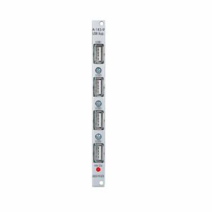
The module has no USB function but provides only the +5V supply for USB devices.
A control LED shows if the +5V are present.
Note: The module requires an A-100 case with built in power supply A-100PSU3. Only this A-100 supply has the required +5V available. We do not recommend the usage of an older A-100 case with A-100PSU2 as this would require the +5V adapter A-100AD5 and the max. current would be limited to 100mA.
quote 711015
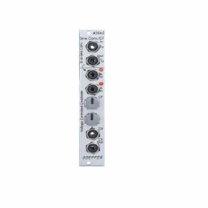
Triangle-to-Sine Waveshaper:
The upper section is a very precise triangle-to-sine converter (thanks to Tim Stinchcombe who recommended this circuit). It can be used to convert any triangle waveform into a (nearly) perfect sine. The converter is much better than the simple diode converter used in the A-110-1, A-111-1, A-145 and A-147-2. Two trimming potentiometers are used to optimize the sine shape. The converter should be assigned to one VCO or LFO because the trimming potentiometers have to be re-adjusted if the input level or DC offset of the input signal changes. If the trimming potentiometers are deliberately mis-adjusted it can be used also as a waveshaper for non-sine waveforms (e.g. sine-shaped at the top of the signal and a peak at the bottom, even voltage controlled by applying an additional voltage to the waveshaping circuit, "circuit-bending" notes will be available).
The waveform converter is DC coupled and can be used also for low frequencies (e.g. LFO triangle waves).
Voltage Controlled Crossfader:
The lower section is a voltage controlled crossfader. It has two inputs A and B. The two signals are mixed together with variable percentage. When the manual control CF is fully CCW only signal A appears at the CF Out socket. When the manual control CF is fully CW only signal B appears at the CF Out socket. In the centre position of the manual control both signal appear with the same level. In addition a control voltage input CV with attenuator is available to enable voltage control of the crossfade.
Two LEDs display the crossfading shares of input A and B.
The crossfader uses two high quality VCAs (SSM2164). Inputs and outputs are DC coupled. Consequently it can be used for audio signals and slowly varying control voltages as well.
The sockets of the upper section (triangle and sine) are normalled to the inputs A and B of the crossfader section. That way the crossfader is used to fade between triangle and sine of the VCO or LFO connected to the waveshaper. If other signals are plugged into the input sockets A and B these signals are used for crossfading.
The main application is to fade between two different waveforms of a VCO or LFO or two different VCF outputs. But the module can be used for any other signals too as the waveshaper and crossfader sections are independent apart from the normalled sockets.
2 in stock $77.35
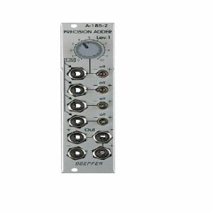
The module is equipped with four CV inputs: one with attenuator and three without attenuator. Each input is normalled to +1 V (i.e. if no plug is inserted the input contributes 1 V to the sum appearing at the output).
The input with attenuator can be used for common modulations (e.g. from an LFO, ADSR, Theremin, Pitch-Bender) for all VCOs connected to the output. The Lev.1 control is used to adjust the depth of the modulation, the first switch selects the polarity of the modulation. If no signal is connected to the first socket the attenuator works as a (fine) tuning knob because a voltage in the range 0...+1V (right position of the switch) or 0...-1V (left position of the switch) is added to the CV output.
The inputs without attenuators are planned to add control voltages coming out of keyboards, sequencers, Midi-to-CV interfaces, ribbon controllers or other CV sources that follow the 1V/oct standard. For example the CV of a keyboard can be used to transpose the CV coming from a sequencer, or the CV of a slow sequencer can be used to transpose the CV from a fast sequencer.
Each input is equipped with a three-position switch that determines if the corresponding voltage is added (right position), subtracted (left position) or if the input has no effect (centre position). If no plug is inserted the corresponding switch works as an octave switch for the lower three sections as the default 1 V are added or subtracted to the output voltage according to the switch position. The first switch can be used to add a variable voltage to the sum output. The variable voltage is adjusted with the Lev.1 control and the knob works then as kind of a (fine) tuning control.
The module is equipped with 4 outputs: three non-inverting and one inverting ouput. An internal jumper can be used to connect the non-inverted or inverted output to the CV line of the A-100 bus. That way the module can used to control several VCOs that are connected to the same bus board as the A-185-2 (same functionality as A-185-1).
1 in stock $76.67
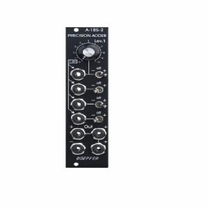
The module is equipped with four CV inputs: one with attenuator and three without attenuator. Each input is normalled to +1 V (i.e. if no plug is inserted the input contributes 1 V to the sum appearing at the output).
The input with attenuator can be used for common modulations (e.g. from an LFO, ADSR, Theremin, Pitch-Bender) for all VCOs connected to the output. The Lev.1 control is used to adjust the depth of the modulation, the first switch selects the polarity of the modulation. If no signal is connected to the first socket the attenuator works as a (fine) tuning knob because a voltage in the range 0...+1V (right position of the switch) or 0...-1V (left position of the switch) is added to the CV output.
The inputs without attenuators are planned to add control voltages coming out of keyboards, sequencers, Midi-to-CV interfaces, ribbon controllers or other CV sources that follow the 1V/oct standard. For example the CV of a keyboard can be used to transpose the CV coming from a sequencer, or the CV of a slow sequencer can be used to transpose the CV from a fast sequencer.
Each input is equipped with a three-position switch that determines if the corresponding voltage is added (right position), subtracted (left position) or if the input has no effect (centre position). If no plug is inserted the corresponding switch works as an octave switch for the lower three sections as the default 1 V are added or subtracted to the output voltage according to the switch position. The first switch can be used to add a variable voltage to the sum output. The variable voltage is adjusted with the Lev.1 control and the knob works then as kind of a (fine) tuning control.
The module is equipped with 4 outputs: three non-inverting and one inverting ouput. An internal jumper can be used to connect the non-inverted or inverted output to the CV line of the A-100 bus. That way the module can used to control several VCOs that are connected to the same bus board as the A-185-2 (same functionality as A-185-1).
Controls:
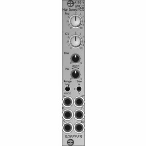
Frq: frequency control (coarse)
CV: attenuator for the frequency control input CV
Fine: frequency control (fine), small control without knob
PW: pulsewidth control for the rectangle output of the audio VCO, in HSVCO mode this control has to be in the range marked "HSVO", small control without knob
Sockets:
1V: frequency control input 1V/oct scale
CV: frequency control input with attenuator CV
socket with rectangle symbol: rectangle output of the audio VCO, the pulse width of this output is adjusted by means of the control PW, output level ~ 7Vpp (~ -3.5V/+3.5V)
socket with sawtooth symbol: sawtooth output of the audio VCO, output level ~ 7Vpp (~ -3.5V ... +3.5V)
socket with triangle symbol: triangle output of the audio VCO, output level ~ 7Vpp (~ -3.5V ... +3.5V)
socket with inverted comb symbol: high speed VCO output, waveform rectangle, output level ~ 5Vpp (~ -2.5V/+2.5V)
Switches:
Range
upper position: audio VCO mode (frequency range of the audio VCO about 15 Hz to 6 kHz, the high speed output is not usable in this mode! )
lower position: High Speed VCO mode (frequency range of the high-speed output about 15 kHz ... 500 kHz, frequency range of the audio VCO about 500 Hz ... 15 kHz), in this mode the audio VCO and the high speed VCO can be used simultaneously
Slew
upper position: medium slew time
centre position: short slew time
lower position: long slew time
Technical Note regarding the Slew parameter:
Besides the audio VCO the module contains a so-called PLL circuit (Phase Locked Loop) and a 1:32 frequency divider. A slew limiter is part of the PLL. It defines how fast the frequency of the PLL follows the frequency of the VCO. The PLL cannot follow the VCO without any delay. Rather one has to find a compromise between the residual ripple of the PLL frequency and the frequency follow rate. That is the job of the slew limiter (works in principle like a glide or portamento unit). For this the module is equipped with a 3-position switch that is used to switch the slew time in 3 ranges. When mostly higher frequencies are used ((~ 100kHz ... 500 kHz) a short slew time can be chosen. When also lower frequencies are required (< 100kHz) a longer slew time may be used to reduce the residual frequency ripple. More details about the working principle of a PLL can be found in the information about module A-196. Module A-188-9 is in principle an A-196 combined with an audio VCO and a 1:32 frequency divider.
Width: 4HP / 20.0 mm
Depth: 45 mm (measured from the rear side of the front panel)
Current: +30 mA (+12V) / -15 mA (-12V)
quote 1046640
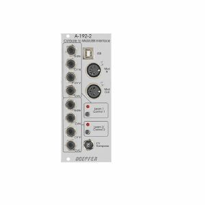
- Gate Input (min. +5V)
- CVN Input (defines the Midi note number), 1V/octave standard, range 0...+10V (i.e. 10 octaves)
- CVV Input (defines the velocity value assigned to the Midi note message), can be used alternatively for Midi volume (CC#7), range 0...+5V
- CVC Input (free assignable to any Midi control change number), range 0...+5V
For both sub-units a common CV Transpose input is available (1V/octave, range 0...+10V). The voltage applied to this input is added internally to CVN before the Midi note number is generated. It can be used e.g. to transpose two sequences simultaneously by one voltage.
How it works:
Whenever the rising edge of the Gate input is recognized a Midi note on message is generated. The note number corresponds to the sum of the voltages applied to the CVN input and the common CV Transpose Input that is present at the rising edge of the gate signal.
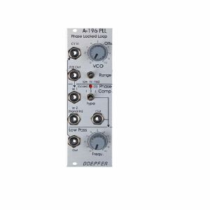
This is how a PLL works: The output of the internal VCO (linear CV control, rectangle output) is compared with an external signal (e.g. the rectangle output of a A-110 VCO) in the so-called phase comparator (PC). The output of the phase comparator is a digital signal (low/high/tristate) that indicates if the frequency resp. phase difference of the two input signals is negative, zero or positive. The output of the phase comparator is processed by a low pass filter (LPF) to generate a smooth voltage that is used to control the frequency of the internal VCO. The 3 units VCO, PC and LPF form a feedback loop that works like this: The control voltage (output of the LPF) increases as long as the external frequency is higher than the frequency of the internal VCO und stops increasing when both frequencies become identical. The control voltage decreases as long as the external frequency is lower than the frequency of the internal VCO und stops decreasing when both frequencies become identical.
But there are some stumbling blocks: Different types of phase comparators with advantages and disadvantages can be made. Some phase comparators e.g. even lock at harmonics, i.e. if the two frequencies to be compared are integer multiples. But for some applications this can be used to create interesting effects. The A-196 contains 3 different types of phase comparators: PC1 is a simple exclusive OR, that even locks at harmonics. PC2 is a so-called RS flipflop and PC3 a more complex digital memory network. The user can select one of the three phase comparators with a 3-position switch. When PC2 is used a LED displays the "locked" state, i.e. when the frequency of the internal VCO is identical to the external frequency.
Special attention has to be directed to the frequency of the LPF. To obtain a smooth control voltage for the VCO the frequency of the LPF has to be much smaller than the lowest frequency of the internal or external audio signal. Otherwise the frequency of the internal VCO will jitter or wobble around the correct frequency. But for special effects this frequency jitter can be used intentionally. Example: frequencies in the range 50Hz...1kHz have to be processed with the PLL. Therefore the frequency of the LPF has to be about 10Hz or even less. Such a low frequency of the LPF causes a noticeable slew of the internal VCO. When the frequency of the external signal jumps e.g. between 500Hz and 1kHz it takes about 0.1 second until the internal VCO reaches the new frequency (like portamento). So one has to find a compromise between frequency jitter and portamento. But these remarks are valid only for the "ideal" working PLL. As the A-196 is used in a musical environment the "problems" and disadvantages with jitter and slew time lead to additional musical applications like portamento effects, wobbling frequencies or harmonic locking according to the type of frequency comparator and time constant of the PLL low pass filter. Instead of the internal manually controlled low pass filter the voltage controlled slew limiter A-171 can be used to obtain voltage control of this parameter. Normal audio filters (e.g. A-120, A-121) cannot be used for this job as the minimum frequency is to high (down to a few Hz or even less necessary) and the signal has to be DC coupled due to the low frequencies. Audio filters are normally AC coupled.
Another very important application of a PLL is frequency multiplication in combination with an external frequency divider. For this the output of the PLL-VCO is processed through an external frequency divider (e.g. A-163, A-160, A-161, A-115) before it is fed to In1 of the phase comparator. In this case the frequency of the PLL-VCO will be a multiple of the master frequency. E.g. if the A-163 is used and adjusted to dividing factor 5 the frequency of the PLL-VCO will be 5 times the frequency of the master VCO. Consequently, frequency division (A-163) leads to frequency multiplication with the PLL circuit. In combination with the PLL low pass frequency several effects can be realized (frequency multiplication with portamento or wobbling). The frequency multiplication can even be used to drive a graphic VCO. If your graphic VCO e.g. has 8 steps (e.g. A-155) and you use a frequency divider with factor 8 in the PLL feedback the output of the graphic VCO has the same frequency as the master VCO. Another application is the generation of pseudo-harmonics (not real harmonics as only rectangle waves are available) or clock generation for switched-capacitor filters.
quote 755416
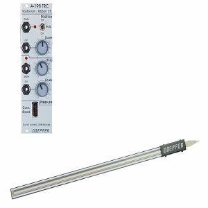
Touching the sensor with a finger generates a control voltage CV1 that is proportional to the position of the finger. The scale (i.e. the relation between position difference and voltage difference) is adjustable with a potentiometer at the front panel. A hold switch is used to determine if the CV voltage is held after removing the finger (hold = on) or if the CV voltage jumps to 0V (hold = off). In the last case (hold = off) a gate signal is derived from the CV voltage whenever a finger touches the sensor (e.g. for triggering an envelope generator).
A sensitive pressure sensor located below the position sensor generates a second control voltage CV2 that increases with higher pressure of the finger. Even for CV2 the scale is adjustable. A second gate signal is triggered as soon as the pressure exceeds a certain value. The gate threshold is adjustable at the front panel.
The sensors are located in a separate metal frame (length about 600 mm, width about 30 mm, height about 18 mm, weight: about 900 g, colour: silver-grey). The connection between the module and the sensor frame is made by a 4 pin cable (same as used for USB connections).
Typical applications:
- Trautonium manual, the string is replaced by the position sensor that is much easier to use and cheaper than the string. In combination with the Subharmonic Oscillator A-113, the Trautonium Filter A-104 and some auxiliary modules a complete Trautonium replica may be realized. In combination with the Quantizer A-156 exact semitone intervals are possible.
- Ribbon Controller for any A-100 parameter
1 in stock $222.56
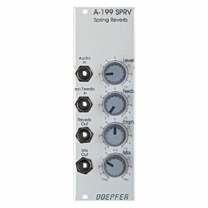
The 3-spring system used in the A-199 ensures a "dense" reverb because of the different properties of the three springs.
The A-199 implies some special features that are not self-evident for spring reverb units:
The reverb signal can be fed back to the input using the Feedback control. Even self-oscillation of the springs similar to the self-oscillation of filters is available. The feedback loop can lead even via external modules like VCA, VCF, phaser, frequency shifter, vocoder, distortion/waveshaper, ring modulator and others. In this case the reverb output of the A-199 is connected to the input of the external module(s) and the output of the external module(s) is fed back to the Ext. Feedback In socket of the A-199. This socket contains a switch that interrupts the internal feedback loop as soon as a plug is inserted.
Another feature is the Emphasis control. This enables the adjustment of the accentuation of middle frequencies (around ~ 2kHz).
With the Mix control the relation between original and reverb signal appearing at the mix output is adjusted.
Using all these features very extreme and unusual effects can be generated with the A-199.

- Length: 1.5 metres
- Length: 3 metres
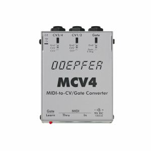
These are the most important MCV4 features:
4 analogue control voltages CV1...CV4
Voltage range for CV1...4: 0...+5V, 8 Bit resolution (equivalent to 1/4 semitone resolution)
CV1 for pitch control (normally VCO CV)
CV2...4 for voltage control of other functions (e.g. VCF frequency, loudness, modulation)
MIDI control of CV1..4:
CV1: note on/off with pitch-bend, 1V/octave characteristic
CV2 monophic after-touch
CV3 velocity and/or volumen (controller #7)
CV4 velocity and/or any controller (setting of the controller number via learn button)
Pitch-bend is used for CV1 generation with 1/4 semitone resolution
Gate output type can be selected via jumper inside the device between voltage trigger (+5V or power supply voltage) and S-trigger (switched trigger)
MIDI channel and reference note for CV1=0V adjustable via learn button
Different assign modes for CV1 (highest note, last note, reference note)
Retrigger on/off while playing legato
Gate/trigger polarity normal/inverted
Two 1/4" stereo jack sockets for CV1/2 and CV3/4
1/4" mono jack socket for gate/trigger
Learn button with LED for adjusting MIDI channel, reference note for CV1, controller for CV4
Optical display of gate/trigger via LED
MIDI-In, MIDI-Thru
Non-volatile memory for parameter settings
Stable metal case (about 95x75x35 mm, 1mm sheet steel)
External AC adapter for power supply
AC adapter for 230V AC and European type of mains connector is included within Europe
7...12V/100mA DC required, DC connector with 5.5 mm outer diameter and 2.1 or 2.5 mm inner diameter, polarity: plus = center, minus = ring
*** Adapters for other parts of the world have to be purchased separately. ***
Suitable accessories:
MCV4 special cable (1/4" stereo jack plug -> 2 x 1/4" mono jack plug, length about 90cm, also called "insert cable")
MIDI channel, reference note for CV1 (this is the MIDI note corresponding to 0V of CV1 and thus the lowest possible note of the analogue synthesizer connected to MCV4) and the controller no. for CV4 are adjusted via learn function. For this, the learn button must be pressed and the required MIDI messages sent from the MIDI controlling device (MIDI synthesizer, keyboard, sequencer ...). The other parameters (retrigger, trigger polarity, assign mode ...) are adjusted in learn mode via program-change messages.
The Hz/V mode available in the predecessor model MCV1 is not available with the MCV4 because of the many problems occurring with the non-linear Hz/V characteristic. But some synthesizers normally using Hz/V can be controlled with V/Oct (e.g. Korg MS10/MS20, details you may find in the MCV4 user's guide).
If you want to use all 4 analogue control voltages, you need 2 special cables with a stereo 1/4" jack plug on one end (MCV4 side) and two mono 1/4" jack plugs on the other (synthesizer side). Cables like this can be purchase elsewhere. If you need it, it is recommended to order it together with the MCV4.
quote 395668