
 USD
USD


Receive new release alerts for Doepfer
Filter

Equipment
Format
Featured
Price
Items 1 to 5 of 5 on page 1 of 1
People also bought...
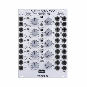
Doepfer A-111-4 Quad Precision VCO Module (silver) (oscillator synth module)
Cat: 671550 Rel: 29 Nov 17
Quad precision voltage contolled oscillator module - 18HP
Notes: A-111-4 contains four precision VCOs and has individual controls, inputs and outputs for each VCO available as well as a common control and output unit. After all the A-111-4 is very similar to four A-111-3 without LFO mode but built in output mixers for the three waveforms, and a master unit for all four VCOs.
Controls, inputs and outputs for each of the four VCOs:
- 1V/Octave CV input
- Octave switch (+1 / 0 / -1 octave)
- Tune control (range internally adjustable by jumpers: ~ 2 semitones / ~ 1 octave / ~ 4 octaves)
- Modulation CV input
- Modulation destination:
- Upper position: exponential frequency modulation (XM)lower position: linear frequency modulation (LM) or pulsewidth modulation of the rectangle (PM), selectable via internal jumper
- Frequency Modulation (FM) or Pulsewidth Modulation of the rectangle (PWM)
- Modulation intensity
- Triangle output
- Sawtooth output
- Rectangle output (about 50% without external PWM)
- Sync input (hard or soft sync internally selectable via jumper, CEM3340 hard sync type)
- Min. 10 octaves range (with appropriate external CV)
- CEM3340 based VCO (triangle core)
- Each VCO has it's own separate internal +/- power supply for each for best stability and the prevention of unwanted synchronisation of the VCOs
Controls, inputs and outputs of the master section:
- 1V/Octave CV input
- Octave switch (+1 / 0 / -1 octave)
- Tune control (range internally adjustable by jumpers: 2 semitones / 1 octave / 4 octaves)
- Frequency Modulation CV input (FM)
- FM intensity
- Triangle sum output
- Sawtooth sum output
- Rectangle sum output
- As soon as the single waveform output of a VCO is patched this waveform of the VCO in question is removed from the sum (this function can be turned off for each single output socket by means of solder bridges on the pc board, i.e. the sum contains then all signals independent of the patching of the single output)
- CV output (outputs the sum CV that is used to control all four VCOs)
- Bus CV (selectable via jumper)
Typical applications:
- Fat sounding monophonic VCO with the possibility to adjust any intervals
- Paraphonic patches in combination with the polyphonic CV interface A-190-5 (all four VCOs processed by one VCF/VCA)
- Full polyphonic patches in combination with the polyphonic CV interface A-190-5 and four complete VCF/VCA sections
- Complex VCO patches with up to four VCOs by means of the frequency modulation features (exponential an linear) and the sync functions
… Read moreControls, inputs and outputs for each of the four VCOs:
- 1V/Octave CV input
- Octave switch (+1 / 0 / -1 octave)
- Tune control (range internally adjustable by jumpers: ~ 2 semitones / ~ 1 octave / ~ 4 octaves)
- Modulation CV input
- Modulation destination:
- Upper position: exponential frequency modulation (XM)lower position: linear frequency modulation (LM) or pulsewidth modulation of the rectangle (PM), selectable via internal jumper
- Frequency Modulation (FM) or Pulsewidth Modulation of the rectangle (PWM)
- Modulation intensity
- Triangle output
- Sawtooth output
- Rectangle output (about 50% without external PWM)
- Sync input (hard or soft sync internally selectable via jumper, CEM3340 hard sync type)
- Min. 10 octaves range (with appropriate external CV)
- CEM3340 based VCO (triangle core)
- Each VCO has it's own separate internal +/- power supply for each for best stability and the prevention of unwanted synchronisation of the VCOs
Controls, inputs and outputs of the master section:
- 1V/Octave CV input
- Octave switch (+1 / 0 / -1 octave)
- Tune control (range internally adjustable by jumpers: 2 semitones / 1 octave / 4 octaves)
- Frequency Modulation CV input (FM)
- FM intensity
- Triangle sum output
- Sawtooth sum output
- Rectangle sum output
- As soon as the single waveform output of a VCO is patched this waveform of the VCO in question is removed from the sum (this function can be turned off for each single output socket by means of solder bridges on the pc board, i.e. the sum contains then all signals independent of the patching of the single output)
- CV output (outputs the sum CV that is used to control all four VCOs)
- Bus CV (selectable via jumper)
Typical applications:
- Fat sounding monophonic VCO with the possibility to adjust any intervals
- Paraphonic patches in combination with the polyphonic CV interface A-190-5 (all four VCOs processed by one VCF/VCA)
- Full polyphonic patches in combination with the polyphonic CV interface A-190-5 and four complete VCF/VCA sections
- Complex VCO patches with up to four VCOs by means of the frequency modulation features (exponential an linear) and the sync functions
1 in stock $380.11
People also bought...
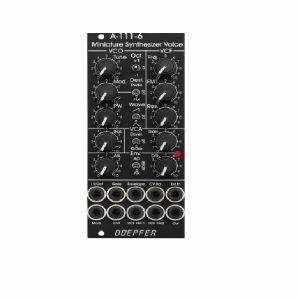
Doepfer A-111-6v Miniature Synthesiser Voice Vintage Edition Module (black) (synth voice synth module)
Cat: 749811 Rel: 15 Nov 19
Complete miniature monophonic synthesiser module - 10HP
Notes: VCO:
- Tune: manual tune control (with an internal jumper the range can be set to ~ +/-1 half an octave or ~ +/-2.5 octaves)
- Oct: range switch -1 / 0 / +1 octave
- Mod: modulation depth (attenuator wired to the Mod. socket)
- Dest: switch that is used to address the modulation to frequency modulation (position FM) or pulsewidth modulation (positon PM), in centre positon no modulation
- PW: manual pulsewidth control for rectangle waveform, PW can be also modulated by the Mod. input as mentioned above
- Wave: waveform switch (sawtooth / off / triangle), the sum of the waveform chosen by this switch and the rectangle is fed into the VCF (to turn the rectangle off the PW control has to be set fully CCW or fully CW)
- 1V/Oct. (socket): external CV input for VCO frequency (1V/octave)
- Access to internal bus CV (via jumper, optional, please remove the bus jumper if this feature is not used to avoid unwanted frequency modulation as then the unused CV line of the bus works as a kind of antenna)
- Triangle core VCO, frequency range about 32Hz ... 8kHz
Balance unit:
- The balance unit is made of two VCAs which are controlled by the sum of manual Balance control and the balance CV input in the opposite direction.
- The audio input of VCA1 is hard-wired to the VCO output, audio input 2 is connected to the socket Ext.In.
- The output of the balance unit is used as audio input for the VCF
- Bal.: manual balance control, fully CCW the internal VCO is used, fully CW the external signal (Ext.In) is used, at centre position both signals have about the same level
- CV Bal.: CV input for balance (range about 0...+5V)
- Ext. In: external audio input for VCA2, about 5 Vpp level required for similar loudness as the internal VCO
- This socket is normalled to the internal VCO suboctave f/2 signal (rectangle with half the frequency), if no external signal is applied the suboctave signal is used as the second signal for the balance unit
VCF:
- 24 dB low pass
- Frq: manual frequency control
- FM1: frequency modulation depth (attenuator wired to the VCF FM1 socket, the socket is normalled to the internal Envelope signal and then FM1 controls the modulation depth of the internal envelope applied to the filter)
- FM2 (socket) : second CV input for VCF without attenuator (about 1V/octave), can be used e.g. for VCF tracking by connecting the same CV which is used also for the VCO frequency
- Res: manual resonance control (up to self oscillation)
- If the VCO is turned off (waveform switch = centre position, pulsewidth control = fully CCW or CW) and the VCF resonance is set to maximum the module can be used as a sine oscillator, the tracking at socket VCF FM2 is about 1V/octave (not as precise as the VCO but much better than most other filters)
- ~ 11 octaves frequency range (~ 10 Hz ... 20kHz)
VCA:
- Gain: manual amplitude control (initial gain), can be used to open the VCA without envelope signal
- VCA (switch): used to switch between gate and envelope as control signal for the VCA, in centre position the VCA is not controlled by envelope or gate
- Note: when gate is used the VCA is controlled directly by the gate signal (i.e. hard on/off), this may lead to clicking noise under certain conditions (especially with low VCO/VCF frequencies)
- Special control scale: exponential scale in the range from about -20dB to -80/90dB, linear scale from about -20dB to 0dB
- Remark: this special control scale results in a loudness behaviour that is a bit different from pure linear or exponential VCAs
- Out: audio output of the module (= VCA output)
Envelope:
- Gate (socket): Gate input (min. +5V), can be normalled to the bus gate signal by means of a jumper
- Att: manual control for Attack
- D/R: manual control for Decay/Release
- Env. (switch): used to switch between A/D, ADSR and A/R mode of the envelope generator, in centre position (ADSR) the sustain level is fixed to about 50%
- Envelope (socket): envelope output (about +10V)
- CVT (socket): CV input for time control, by means of two internal jumpers one can select which time parameters are controlled by the CVT input (e.g. A only or D/R only or A/D/R) and in which direction (i.e. if an increasing CVT shortens or stretches the time parameter in question)
- Envelope LED display
- Attack time range: ~ 1ms ... 5 sec (can be extended by using the CVT input)
- Decay/Release time range: ~ 1ms ... 15 sec (can be extended by using the CVT input)
… Read more- Tune: manual tune control (with an internal jumper the range can be set to ~ +/-1 half an octave or ~ +/-2.5 octaves)
- Oct: range switch -1 / 0 / +1 octave
- Mod: modulation depth (attenuator wired to the Mod. socket)
- Dest: switch that is used to address the modulation to frequency modulation (position FM) or pulsewidth modulation (positon PM), in centre positon no modulation
- PW: manual pulsewidth control for rectangle waveform, PW can be also modulated by the Mod. input as mentioned above
- Wave: waveform switch (sawtooth / off / triangle), the sum of the waveform chosen by this switch and the rectangle is fed into the VCF (to turn the rectangle off the PW control has to be set fully CCW or fully CW)
- 1V/Oct. (socket): external CV input for VCO frequency (1V/octave)
- Access to internal bus CV (via jumper, optional, please remove the bus jumper if this feature is not used to avoid unwanted frequency modulation as then the unused CV line of the bus works as a kind of antenna)
- Triangle core VCO, frequency range about 32Hz ... 8kHz
Balance unit:
- The balance unit is made of two VCAs which are controlled by the sum of manual Balance control and the balance CV input in the opposite direction.
- The audio input of VCA1 is hard-wired to the VCO output, audio input 2 is connected to the socket Ext.In.
- The output of the balance unit is used as audio input for the VCF
- Bal.: manual balance control, fully CCW the internal VCO is used, fully CW the external signal (Ext.In) is used, at centre position both signals have about the same level
- CV Bal.: CV input for balance (range about 0...+5V)
- Ext. In: external audio input for VCA2, about 5 Vpp level required for similar loudness as the internal VCO
- This socket is normalled to the internal VCO suboctave f/2 signal (rectangle with half the frequency), if no external signal is applied the suboctave signal is used as the second signal for the balance unit
VCF:
- 24 dB low pass
- Frq: manual frequency control
- FM1: frequency modulation depth (attenuator wired to the VCF FM1 socket, the socket is normalled to the internal Envelope signal and then FM1 controls the modulation depth of the internal envelope applied to the filter)
- FM2 (socket) : second CV input for VCF without attenuator (about 1V/octave), can be used e.g. for VCF tracking by connecting the same CV which is used also for the VCO frequency
- Res: manual resonance control (up to self oscillation)
- If the VCO is turned off (waveform switch = centre position, pulsewidth control = fully CCW or CW) and the VCF resonance is set to maximum the module can be used as a sine oscillator, the tracking at socket VCF FM2 is about 1V/octave (not as precise as the VCO but much better than most other filters)
- ~ 11 octaves frequency range (~ 10 Hz ... 20kHz)
VCA:
- Gain: manual amplitude control (initial gain), can be used to open the VCA without envelope signal
- VCA (switch): used to switch between gate and envelope as control signal for the VCA, in centre position the VCA is not controlled by envelope or gate
- Note: when gate is used the VCA is controlled directly by the gate signal (i.e. hard on/off), this may lead to clicking noise under certain conditions (especially with low VCO/VCF frequencies)
- Special control scale: exponential scale in the range from about -20dB to -80/90dB, linear scale from about -20dB to 0dB
- Remark: this special control scale results in a loudness behaviour that is a bit different from pure linear or exponential VCAs
- Out: audio output of the module (= VCA output)
Envelope:
- Gate (socket): Gate input (min. +5V), can be normalled to the bus gate signal by means of a jumper
- Att: manual control for Attack
- D/R: manual control for Decay/Release
- Env. (switch): used to switch between A/D, ADSR and A/R mode of the envelope generator, in centre position (ADSR) the sustain level is fixed to about 50%
- Envelope (socket): envelope output (about +10V)
- CVT (socket): CV input for time control, by means of two internal jumpers one can select which time parameters are controlled by the CVT input (e.g. A only or D/R only or A/D/R) and in which direction (i.e. if an increasing CVT shortens or stretches the time parameter in question)
- Envelope LED display
- Attack time range: ~ 1ms ... 5 sec (can be extended by using the CVT input)
- Decay/Release time range: ~ 1ms ... 15 sec (can be extended by using the CVT input)
1 in stock $207.73
People also bought...
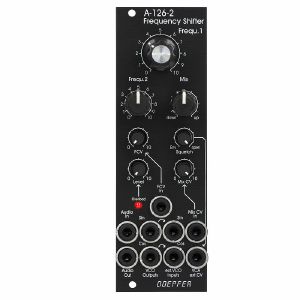
Doepfer A-126-2v Frequency Shifter Module (vintage edition) (sound processor synth module)
Cat: 847083 Rel: 17 Nov 21
Voltage controlled frequency shifter module -
Notes: 'Vintage' black panel version of Doepfer's updated frequency shifter module, offering weird and wonderful effects by shifting all frequencies by a fixed amount. Unique sound, not to be confused with pitch shifting.
Supplier's Notes:
Module A-126-2 is a fully analog frequency shifter for audio signals. A frequency shifter is an audio processing unit that shifts each frequency of the incoming audio signal by the same frequency. If the shifting frequency is e.g. 200Hz an incoming audio frequency of 1000 Hz becomes 1200 Hz, 2000Hz becomes 2200 Hz, 3000 Hz becomes 3200 Hz and so on. Pay attention that this is different from pitch shifting where all frequencies are shifted proportional (e.g. 1000>1200Hz, 2000>2400Hz, 3000>3600Hz) !
The frequency range of the internal quadrature VCO is about 8 octaves (about 20Hz ... 5kHz). If required an external quadrature VCO can be used.
The module is equipped with these controls, inputs and outputs:
Frequ. 1: first manual control of the shifting frequency (factory setting: coarse, range about 20Hz - 5 kHz)
Frequ. 2: second manual control of the shifting frequency (factory setting: fine)
by means of internal jumpers the sensitivity of Frequ.1 and 2 can be swapped (i.e. Frequ.1 = fine and Frequ.2 = coarse)
the relation between coarse and fine control is about 25:1 (corresponding to about 8 octaves to 1/3 octave)
FCV In (socket) and FCV (small control without knob): control voltage input with attenuator for the external voltage control of the shifting frequency
Mix: manual control of the up/down shift panning unit, fully CCW = down shift, fully CW = up shift, in between a mixture of down and up
Mix CV In (socket) and Mix CV (small control without knob): control voltage input with attenuator for the mixing unit for external voltage control of the up/down mixing
Audio In (socket), Level (small control without knob) and Overload (LED): audio input with attenuator, typ. audio in level = 1Vpp, the level control has to be adjusted so that the overload LED just begins to light up a bit, when the LED is fully on clipping/distortion occurs, when the LED is permanently off the input level is too low and the signal-to-noise ratio increases
Audio Out (socket): audio output of the frequency shifter
Squelch (small control without knob): controls the squelch function: fully CCW (Env.) the output VCA is controlled by the envelope signal, which is derived from the audio input signal, fully CW (open) the output VCA is permanently open (no squelch function), in between the squelch intensity can be adjusted
Quadrature VCO Outputs (sockets Sin and Cos): outputs of the internal quadrature oscillator, about 12Vpp level (+6V/-6V)
Ext. Inputs Sin and Cos (sockets): required when an external quadrature VCO (e.g. A-143-9 with a wider frequency range or A-110-4 with thru zero feature or A-110-6 with different waveforms) is used instead of the internal quadrature VCO, the levels of the external VCO should be about 10Vpp (8...10Vpp are OK) and the signals have to be symmetrical around zero Volts, the sockets are normalled to the internal quadrature VCO (i.e. the sockets are equipped with switching contacts that interrupt the internal connection as soon as a plug inserted)
VCA ext. CV (socket): used when an external control voltage (e.g. from an envelope generator) should be used to control the output VCA instead of the internal squelch unit, the socket is normalled to the output of the squelch control (i.e. the socket is equipped with a switching contact that interrupts the internal squelch connection as soon as a plug inserted). From about +8V external control voltage the VCA is fully open.
Internal terminals (pin headers, e.g. for a DIY breakout module):
envelope follower output
dome filter output 1
dome filter output 2
ring modulator 1 output
ring modulator 2 output
Up shift output
Down shift output
… Read moreSupplier's Notes:
Module A-126-2 is a fully analog frequency shifter for audio signals. A frequency shifter is an audio processing unit that shifts each frequency of the incoming audio signal by the same frequency. If the shifting frequency is e.g. 200Hz an incoming audio frequency of 1000 Hz becomes 1200 Hz, 2000Hz becomes 2200 Hz, 3000 Hz becomes 3200 Hz and so on. Pay attention that this is different from pitch shifting where all frequencies are shifted proportional (e.g. 1000>1200Hz, 2000>2400Hz, 3000>3600Hz) !
The frequency range of the internal quadrature VCO is about 8 octaves (about 20Hz ... 5kHz). If required an external quadrature VCO can be used.
The module is equipped with these controls, inputs and outputs:
Frequ. 1: first manual control of the shifting frequency (factory setting: coarse, range about 20Hz - 5 kHz)
Frequ. 2: second manual control of the shifting frequency (factory setting: fine)
by means of internal jumpers the sensitivity of Frequ.1 and 2 can be swapped (i.e. Frequ.1 = fine and Frequ.2 = coarse)
the relation between coarse and fine control is about 25:1 (corresponding to about 8 octaves to 1/3 octave)
FCV In (socket) and FCV (small control without knob): control voltage input with attenuator for the external voltage control of the shifting frequency
Mix: manual control of the up/down shift panning unit, fully CCW = down shift, fully CW = up shift, in between a mixture of down and up
Mix CV In (socket) and Mix CV (small control without knob): control voltage input with attenuator for the mixing unit for external voltage control of the up/down mixing
Audio In (socket), Level (small control without knob) and Overload (LED): audio input with attenuator, typ. audio in level = 1Vpp, the level control has to be adjusted so that the overload LED just begins to light up a bit, when the LED is fully on clipping/distortion occurs, when the LED is permanently off the input level is too low and the signal-to-noise ratio increases
Audio Out (socket): audio output of the frequency shifter
Squelch (small control without knob): controls the squelch function: fully CCW (Env.) the output VCA is controlled by the envelope signal, which is derived from the audio input signal, fully CW (open) the output VCA is permanently open (no squelch function), in between the squelch intensity can be adjusted
Quadrature VCO Outputs (sockets Sin and Cos): outputs of the internal quadrature oscillator, about 12Vpp level (+6V/-6V)
Ext. Inputs Sin and Cos (sockets): required when an external quadrature VCO (e.g. A-143-9 with a wider frequency range or A-110-4 with thru zero feature or A-110-6 with different waveforms) is used instead of the internal quadrature VCO, the levels of the external VCO should be about 10Vpp (8...10Vpp are OK) and the signals have to be symmetrical around zero Volts, the sockets are normalled to the internal quadrature VCO (i.e. the sockets are equipped with switching contacts that interrupt the internal connection as soon as a plug inserted)
VCA ext. CV (socket): used when an external control voltage (e.g. from an envelope generator) should be used to control the output VCA instead of the internal squelch unit, the socket is normalled to the output of the squelch control (i.e. the socket is equipped with a switching contact that interrupts the internal squelch connection as soon as a plug inserted). From about +8V external control voltage the VCA is fully open.
Internal terminals (pin headers, e.g. for a DIY breakout module):
envelope follower output
dome filter output 1
dome filter output 2
ring modulator 1 output
ring modulator 2 output
Up shift output
Down shift output
1 in stock $334.43
People also bought...
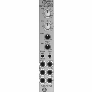
Doepfer A-188-9 HVCO High-Speed VCO Module (oscillator synth module)
Cat: 1046640 Rel: 12 Feb 25
High-speed voltage controlled oscillator module - 4HP
Notes: Module A-188-9 is a so-called high speed VCO that tracks perfectly to the 1V/oct scale in the frequency range of about 15kHz ... 500 kHz. The main application is the exact drive of BBD modules (A-188-1/2) to generate sounds realized by means of the so-called Karplus-Strong synthesis. But even in cooperation with other modules featuring high speed inputs (e.g. digital noise, delay, frequency divider) the A-188-9 makes sense. In principle the module is made of a precision audio VCO followed by a PLL (phase locked loop) unit that multiplies the frequency of the audio VCO by 32. Thus the module can be used also as an audio VCO as it features the standard waveforms sawtooth, triangle and rectangle with adjustable pulse width.
Controls:
Frq: frequency control (coarse)
CV: attenuator for the frequency control input CV
Fine: frequency control (fine), small control without knob
PW: pulsewidth control for the rectangle output of the audio VCO, in HSVCO mode this control has to be in the range marked "HSVO", small control without knob
Sockets:
1V: frequency control input 1V/oct scale
CV: frequency control input with attenuator CV
socket with rectangle symbol: rectangle output of the audio VCO, the pulse width of this output is adjusted by means of the control PW, output level ~ 7Vpp (~ -3.5V/+3.5V)
socket with sawtooth symbol: sawtooth output of the audio VCO, output level ~ 7Vpp (~ -3.5V ... +3.5V)
socket with triangle symbol: triangle output of the audio VCO, output level ~ 7Vpp (~ -3.5V ... +3.5V)
socket with inverted comb symbol: high speed VCO output, waveform rectangle, output level ~ 5Vpp (~ -2.5V/+2.5V)
Switches:
Range
upper position: audio VCO mode (frequency range of the audio VCO about 15 Hz to 6 kHz, the high speed output is not usable in this mode! )
lower position: High Speed VCO mode (frequency range of the high-speed output about 15 kHz ... 500 kHz, frequency range of the audio VCO about 500 Hz ... 15 kHz), in this mode the audio VCO and the high speed VCO can be used simultaneously
Slew
upper position: medium slew time
centre position: short slew time
lower position: long slew time
Technical Note regarding the Slew parameter:
Besides the audio VCO the module contains a so-called PLL circuit (Phase Locked Loop) and a 1:32 frequency divider. A slew limiter is part of the PLL. It defines how fast the frequency of the PLL follows the frequency of the VCO. The PLL cannot follow the VCO without any delay. Rather one has to find a compromise between the residual ripple of the PLL frequency and the frequency follow rate. That is the job of the slew limiter (works in principle like a glide or portamento unit). For this the module is equipped with a 3-position switch that is used to switch the slew time in 3 ranges. When mostly higher frequencies are used ((~ 100kHz ... 500 kHz) a short slew time can be chosen. When also lower frequencies are required (< 100kHz) a longer slew time may be used to reduce the residual frequency ripple. More details about the working principle of a PLL can be found in the information about module A-196. Module A-188-9 is in principle an A-196 combined with an audio VCO and a 1:32 frequency divider.
Width: 4HP / 20.0 mm
Depth: 45 mm (measured from the rear side of the front panel)
Current: +30 mA (+12V) / -15 mA (-12V)
… Read moreControls:
Frq: frequency control (coarse)
CV: attenuator for the frequency control input CV
Fine: frequency control (fine), small control without knob
PW: pulsewidth control for the rectangle output of the audio VCO, in HSVCO mode this control has to be in the range marked "HSVO", small control without knob
Sockets:
1V: frequency control input 1V/oct scale
CV: frequency control input with attenuator CV
socket with rectangle symbol: rectangle output of the audio VCO, the pulse width of this output is adjusted by means of the control PW, output level ~ 7Vpp (~ -3.5V/+3.5V)
socket with sawtooth symbol: sawtooth output of the audio VCO, output level ~ 7Vpp (~ -3.5V ... +3.5V)
socket with triangle symbol: triangle output of the audio VCO, output level ~ 7Vpp (~ -3.5V ... +3.5V)
socket with inverted comb symbol: high speed VCO output, waveform rectangle, output level ~ 5Vpp (~ -2.5V/+2.5V)
Switches:
Range
upper position: audio VCO mode (frequency range of the audio VCO about 15 Hz to 6 kHz, the high speed output is not usable in this mode! )
lower position: High Speed VCO mode (frequency range of the high-speed output about 15 kHz ... 500 kHz, frequency range of the audio VCO about 500 Hz ... 15 kHz), in this mode the audio VCO and the high speed VCO can be used simultaneously
Slew
upper position: medium slew time
centre position: short slew time
lower position: long slew time
Technical Note regarding the Slew parameter:
Besides the audio VCO the module contains a so-called PLL circuit (Phase Locked Loop) and a 1:32 frequency divider. A slew limiter is part of the PLL. It defines how fast the frequency of the PLL follows the frequency of the VCO. The PLL cannot follow the VCO without any delay. Rather one has to find a compromise between the residual ripple of the PLL frequency and the frequency follow rate. That is the job of the slew limiter (works in principle like a glide or portamento unit). For this the module is equipped with a 3-position switch that is used to switch the slew time in 3 ranges. When mostly higher frequencies are used ((~ 100kHz ... 500 kHz) a short slew time can be chosen. When also lower frequencies are required (< 100kHz) a longer slew time may be used to reduce the residual frequency ripple. More details about the working principle of a PLL can be found in the information about module A-196. Module A-188-9 is in principle an A-196 combined with an audio VCO and a 1:32 frequency divider.
Width: 4HP / 20.0 mm
Depth: 45 mm (measured from the rear side of the front panel)
Current: +30 mA (+12V) / -15 mA (-12V)
3 in stock $141.43
Click for better price!
or call +44 20 7424 1960
quote 1046640
quote 1046640
People also bought...
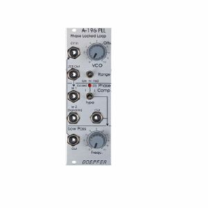
Doepfer A-196 PLL Phase Locked Loop Module (processing synth module)
Cat: 755416 Rel: 14 Nov 19
Eurorack phase locked loop module, featuring voltage-controlled oscillator, phase comparator & low pass filter
Notes: Module A-196 contains a so-called phase locked loop (PLL). The basic PLL system is shown in the sketch at the bottom of this page. A PLL consists of three parts: voltage-controlled oscillator (VCO), phase comparator (PC), and low-pass filter (LPF). All parts are normally connected to form a closed-loop frequency-feedback system.
This is how a PLL works: The output of the internal VCO (linear CV control, rectangle output) is compared with an external signal (e.g. the rectangle output of a A-110 VCO) in the so-called phase comparator (PC). The output of the phase comparator is a digital signal (low/high/tristate) that indicates if the frequency resp. phase difference of the two input signals is negative, zero or positive. The output of the phase comparator is processed by a low pass filter (LPF) to generate a smooth voltage that is used to control the frequency of the internal VCO. The 3 units VCO, PC and LPF form a feedback loop that works like this: The control voltage (output of the LPF) increases as long as the external frequency is higher than the frequency of the internal VCO und stops increasing when both frequencies become identical. The control voltage decreases as long as the external frequency is lower than the frequency of the internal VCO und stops decreasing when both frequencies become identical.
But there are some stumbling blocks: Different types of phase comparators with advantages and disadvantages can be made. Some phase comparators e.g. even lock at harmonics, i.e. if the two frequencies to be compared are integer multiples. But for some applications this can be used to create interesting effects. The A-196 contains 3 different types of phase comparators: PC1 is a simple exclusive OR, that even locks at harmonics. PC2 is a so-called RS flipflop and PC3 a more complex digital memory network. The user can select one of the three phase comparators with a 3-position switch. When PC2 is used a LED displays the "locked" state, i.e. when the frequency of the internal VCO is identical to the external frequency.
Special attention has to be directed to the frequency of the LPF. To obtain a smooth control voltage for the VCO the frequency of the LPF has to be much smaller than the lowest frequency of the internal or external audio signal. Otherwise the frequency of the internal VCO will jitter or wobble around the correct frequency. But for special effects this frequency jitter can be used intentionally. Example: frequencies in the range 50Hz...1kHz have to be processed with the PLL. Therefore the frequency of the LPF has to be about 10Hz or even less. Such a low frequency of the LPF causes a noticeable slew of the internal VCO. When the frequency of the external signal jumps e.g. between 500Hz and 1kHz it takes about 0.1 second until the internal VCO reaches the new frequency (like portamento). So one has to find a compromise between frequency jitter and portamento. But these remarks are valid only for the "ideal" working PLL. As the A-196 is used in a musical environment the "problems" and disadvantages with jitter and slew time lead to additional musical applications like portamento effects, wobbling frequencies or harmonic locking according to the type of frequency comparator and time constant of the PLL low pass filter. Instead of the internal manually controlled low pass filter the voltage controlled slew limiter A-171 can be used to obtain voltage control of this parameter. Normal audio filters (e.g. A-120, A-121) cannot be used for this job as the minimum frequency is to high (down to a few Hz or even less necessary) and the signal has to be DC coupled due to the low frequencies. Audio filters are normally AC coupled.
Another very important application of a PLL is frequency multiplication in combination with an external frequency divider. For this the output of the PLL-VCO is processed through an external frequency divider (e.g. A-163, A-160, A-161, A-115) before it is fed to In1 of the phase comparator. In this case the frequency of the PLL-VCO will be a multiple of the master frequency. E.g. if the A-163 is used and adjusted to dividing factor 5 the frequency of the PLL-VCO will be 5 times the frequency of the master VCO. Consequently, frequency division (A-163) leads to frequency multiplication with the PLL circuit. In combination with the PLL low pass frequency several effects can be realized (frequency multiplication with portamento or wobbling). The frequency multiplication can even be used to drive a graphic VCO. If your graphic VCO e.g. has 8 steps (e.g. A-155) and you use a frequency divider with factor 8 in the PLL feedback the output of the graphic VCO has the same frequency as the master VCO. Another application is the generation of pseudo-harmonics (not real harmonics as only rectangle waves are available) or clock generation for switched-capacitor filters.
… Read moreThis is how a PLL works: The output of the internal VCO (linear CV control, rectangle output) is compared with an external signal (e.g. the rectangle output of a A-110 VCO) in the so-called phase comparator (PC). The output of the phase comparator is a digital signal (low/high/tristate) that indicates if the frequency resp. phase difference of the two input signals is negative, zero or positive. The output of the phase comparator is processed by a low pass filter (LPF) to generate a smooth voltage that is used to control the frequency of the internal VCO. The 3 units VCO, PC and LPF form a feedback loop that works like this: The control voltage (output of the LPF) increases as long as the external frequency is higher than the frequency of the internal VCO und stops increasing when both frequencies become identical. The control voltage decreases as long as the external frequency is lower than the frequency of the internal VCO und stops decreasing when both frequencies become identical.
But there are some stumbling blocks: Different types of phase comparators with advantages and disadvantages can be made. Some phase comparators e.g. even lock at harmonics, i.e. if the two frequencies to be compared are integer multiples. But for some applications this can be used to create interesting effects. The A-196 contains 3 different types of phase comparators: PC1 is a simple exclusive OR, that even locks at harmonics. PC2 is a so-called RS flipflop and PC3 a more complex digital memory network. The user can select one of the three phase comparators with a 3-position switch. When PC2 is used a LED displays the "locked" state, i.e. when the frequency of the internal VCO is identical to the external frequency.
Special attention has to be directed to the frequency of the LPF. To obtain a smooth control voltage for the VCO the frequency of the LPF has to be much smaller than the lowest frequency of the internal or external audio signal. Otherwise the frequency of the internal VCO will jitter or wobble around the correct frequency. But for special effects this frequency jitter can be used intentionally. Example: frequencies in the range 50Hz...1kHz have to be processed with the PLL. Therefore the frequency of the LPF has to be about 10Hz or even less. Such a low frequency of the LPF causes a noticeable slew of the internal VCO. When the frequency of the external signal jumps e.g. between 500Hz and 1kHz it takes about 0.1 second until the internal VCO reaches the new frequency (like portamento). So one has to find a compromise between frequency jitter and portamento. But these remarks are valid only for the "ideal" working PLL. As the A-196 is used in a musical environment the "problems" and disadvantages with jitter and slew time lead to additional musical applications like portamento effects, wobbling frequencies or harmonic locking according to the type of frequency comparator and time constant of the PLL low pass filter. Instead of the internal manually controlled low pass filter the voltage controlled slew limiter A-171 can be used to obtain voltage control of this parameter. Normal audio filters (e.g. A-120, A-121) cannot be used for this job as the minimum frequency is to high (down to a few Hz or even less necessary) and the signal has to be DC coupled due to the low frequencies. Audio filters are normally AC coupled.
Another very important application of a PLL is frequency multiplication in combination with an external frequency divider. For this the output of the PLL-VCO is processed through an external frequency divider (e.g. A-163, A-160, A-161, A-115) before it is fed to In1 of the phase comparator. In this case the frequency of the PLL-VCO will be a multiple of the master frequency. E.g. if the A-163 is used and adjusted to dividing factor 5 the frequency of the PLL-VCO will be 5 times the frequency of the master VCO. Consequently, frequency division (A-163) leads to frequency multiplication with the PLL circuit. In combination with the PLL low pass frequency several effects can be realized (frequency multiplication with portamento or wobbling). The frequency multiplication can even be used to drive a graphic VCO. If your graphic VCO e.g. has 8 steps (e.g. A-155) and you use a frequency divider with factor 8 in the PLL feedback the output of the graphic VCO has the same frequency as the master VCO. Another application is the generation of pseudo-harmonics (not real harmonics as only rectangle waves are available) or clock generation for switched-capacitor filters.
1 in stock $83.98
Click for better price!
or call +44 20 7424 1960
quote 755416
quote 755416
Items 1 to 5 of 5 on page 1 of 1