
 USD
USD


Receive new release alerts for Doepfer
Filter

Equipment
Format
Featured
Price
Items 1 to 4 of 4 on page 1 of 1
People also bought...
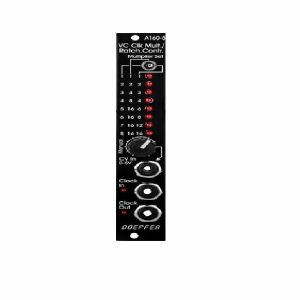
Doepfer A-160-5v Voltage Controlled Clock Multiplier & Ratcheting Controller Module (vintage edition) (synth module)
Cat: 745789 Rel: 10 Sep 19
Voltage-controlled clock multiplier with CV or manual control - 4HP
Notes: Module A-160-5 is a voltage controlled clock multiplier. The incoming clock signal (socket Clock In) is multiplied by a factor that depends upon the control voltage on socket CV In (0...+5V) and the position of the Mode switch. The multiplied clock signal is available at the socket Clock Out. According to the position of the Mode switch different clock multiplying factors are assigned to the control voltage. With 0V CV no clock output is generated. This state is indicated by "all LEDs off". With increasing CV integer factors (left position of the mode switch), power of two factors (middle position) or a mix of both (right position) are obtained. Nine LEDs are used to show the currently selected multiplying factor. In addition two LEDs are used to display the incoming and outgoing clock signal.
A manual control is used to adjust the clock multiplication factor manually without the need of an external control voltage. The voltage generated by this control ("Manual") is normalled to the CV In socket. As long as no plug is inserted into the CV In socket the clock multiplication factor is adjusted by means of the manual control knob and displayed by the LEDs. For dynamic applications (like the ratcheting function described below) the manually generated CV is overwritten by the external CV which has to be fed into the CV In socket.
The module can be used for all kind of clock multiplying applications. One important example is the generation of so-called ratcheting sequences. The band Tangerine Dream is famous for this kind of sequences. A normal sequencer generates only one gate signal per step. A ratcheting sequence may have also more than one gate pulses per step. This function can be obtained by using the A-160-5: one CV output of the sequencer is used to define the number of gate pulses per step. If the control of the step in question is fully CCW the generated CV is 0V and no gate signal is generated (mute of the step). When the control of the step in question is turned clockwise one, two or more gate pulses are generated depending upon the position of the mode switch and the voltage generated by the CV at this step.
Technical note: Due to the nature of clock multiplying it takes a few input clock pulses until the clock output is stable. One has to average a few input clock pulses to generate the multiplied clock output signal. Even when the input clock frequency changes it will take a few cycles until the output clock signal is correct as the module cannot foresee the future of the clock input signal. The generated clock output signal is derived from the last few cycles of the clock input signal. Consequently the module should be driven only by a clock signal with constant or slowly changing frequency.
… Read moreA manual control is used to adjust the clock multiplication factor manually without the need of an external control voltage. The voltage generated by this control ("Manual") is normalled to the CV In socket. As long as no plug is inserted into the CV In socket the clock multiplication factor is adjusted by means of the manual control knob and displayed by the LEDs. For dynamic applications (like the ratcheting function described below) the manually generated CV is overwritten by the external CV which has to be fed into the CV In socket.
The module can be used for all kind of clock multiplying applications. One important example is the generation of so-called ratcheting sequences. The band Tangerine Dream is famous for this kind of sequences. A normal sequencer generates only one gate signal per step. A ratcheting sequence may have also more than one gate pulses per step. This function can be obtained by using the A-160-5: one CV output of the sequencer is used to define the number of gate pulses per step. If the control of the step in question is fully CCW the generated CV is 0V and no gate signal is generated (mute of the step). When the control of the step in question is turned clockwise one, two or more gate pulses are generated depending upon the position of the mode switch and the voltage generated by the CV at this step.
Technical note: Due to the nature of clock multiplying it takes a few input clock pulses until the clock output is stable. One has to average a few input clock pulses to generate the multiplied clock output signal. Even when the input clock frequency changes it will take a few cycles until the output clock signal is correct as the module cannot foresee the future of the clock input signal. The generated clock output signal is derived from the last few cycles of the clock input signal. Consequently the module should be driven only by a clock signal with constant or slowly changing frequency.
1 in stock $114.91
Click for better price!
or call +44 20 7424 1960
quote 745789
quote 745789
People also bought...
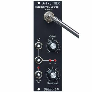
Doepfer A-178v Theremin Control Voltage Source Module (vintage edition) (modulation synth module)
Cat: 852800 Rel: 05 Jan 22
Theremin module for generating a variable control voltage by approaching/removing hand to/from an antenna.
Notes: Theremin module for generating a variable control voltage by approaching/removing hand to/from an antenna.
The distance range is about 30 cm. Additionally the module is equipped with a Gate output with adjustable threshold level. To simulate the original Theremin two A-178, a VCO (e.g. A-110) and a linear VCA (e.g. A-130 or A-132) are required. But of course the A-178 can be used to control other functions in the A-100 (e.g. filter frequency, modulation depth and/or speed, tempo, attack/decay time and so on).
The CV output voltage of the A-178 can range - according to the setting of the front panel controls - from -10V...+10V.
The gate output switches from 0V to about +10V.
Power consumption: 60mA at +12V and 20mA at -12V
Depth: 40mm
HP : 8
… Read moreThe distance range is about 30 cm. Additionally the module is equipped with a Gate output with adjustable threshold level. To simulate the original Theremin two A-178, a VCO (e.g. A-110) and a linear VCA (e.g. A-130 or A-132) are required. But of course the A-178 can be used to control other functions in the A-100 (e.g. filter frequency, modulation depth and/or speed, tempo, attack/decay time and so on).
The CV output voltage of the A-178 can range - according to the setting of the front panel controls - from -10V...+10V.
The gate output switches from 0V to about +10V.
Power consumption: 60mA at +12V and 20mA at -12V
Depth: 40mm
HP : 8
1 in stock $113.81
Click for better price!
or call +44 20 7424 1960
quote 852800
quote 852800
People also bought...
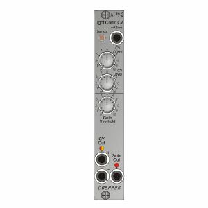
Doepfer A-179-2 Light Controlled Voltage Source II Slim Line Series Module (silver) (controller synth module)
Cat: 847090 Rel: 09 Nov 21
Light Controlled Voltage Source II (Slim Line Series)
Notes: Module A-179-2 can be used to convert different illumination intensities into corresponding analog voltages and a gate signal derived from the analog voltage. It's the successor of the obsolete module A-179.
A light sensitive resistor (LDR) converts the illumination of the internal light sensor into a corresponding analog control voltage. The internal sensor is located at the front panel. Instead of the internal sensor a remote sensor can be connected via a standard patch cable to the module (ext.Sens. socket). An external sensor with a 2 m patch cable (A-100C200) is included. The external sensor is mounted on a small pc board which is equipped also with a 3.5 mm jack socket. The nut of the socket can also be used to mount the external sensor.
The module A-179 is similar to the Theremin module A-178 but uses the illumination intensity instead of the distance between hand and antenna for generating the analog voltage.
One can choose between passive control by covering/shading the sensor via hand or body, or active control by using e.g. a pocket lamp or flashlight. For this two versions of output voltages are available (CV Out + und CV Out -).
The module has these controls and in/outputs available:
ext. Sens.: by means of a standard patch cable the external sensor can be connected to this socket. In this case the internal sensor is turned off.
CV Offset: control to adjust the output voltage which is assigned to a certain illumination (e.g. 0V for complete darkness)
CV Level: control that is used to adjust the sensitivity of the generated output voltage (i.e. how much a certain difference in brightness affects the output voltage)
Gate Threshold: control that is used to adjust the threshold for the generation of the gate signal, an internal jumper is used to define if the gate signal is derived from the CV Out+ or CV Out- voltage.
CV Out+: positive control voltage output, increasing brighness causes the increase of the voltage at this output
CV Out+: negative control voltage output, increasing brighness causes the decrease of the voltage at this output
LED CV Out: bipolar LED (red/yellow) as display for the CV outputs
Gate: gate output with LED display
Applications:
controlling any voltage controlled parameter e.g. pitch or pulswidth of a VCO, filter frequency or resonance of a VCF, loudness of a VCA, time of an envelope generator, frequency of a VCLFO
triggering activities via gate with adjustable threshold, e.g. starting an envelope, starting/stopping a sequencer or any switching function (e.g. with A-150-1 or 151).
Conversion into MIDI control change messages is possible with the A-192-2.
Width: 4 HP / 20.0 mm
Depth: 30mm (measured from the rear side of the front panel)
… Read moreA light sensitive resistor (LDR) converts the illumination of the internal light sensor into a corresponding analog control voltage. The internal sensor is located at the front panel. Instead of the internal sensor a remote sensor can be connected via a standard patch cable to the module (ext.Sens. socket). An external sensor with a 2 m patch cable (A-100C200) is included. The external sensor is mounted on a small pc board which is equipped also with a 3.5 mm jack socket. The nut of the socket can also be used to mount the external sensor.
The module A-179 is similar to the Theremin module A-178 but uses the illumination intensity instead of the distance between hand and antenna for generating the analog voltage.
One can choose between passive control by covering/shading the sensor via hand or body, or active control by using e.g. a pocket lamp or flashlight. For this two versions of output voltages are available (CV Out + und CV Out -).
The module has these controls and in/outputs available:
ext. Sens.: by means of a standard patch cable the external sensor can be connected to this socket. In this case the internal sensor is turned off.
CV Offset: control to adjust the output voltage which is assigned to a certain illumination (e.g. 0V for complete darkness)
CV Level: control that is used to adjust the sensitivity of the generated output voltage (i.e. how much a certain difference in brightness affects the output voltage)
Gate Threshold: control that is used to adjust the threshold for the generation of the gate signal, an internal jumper is used to define if the gate signal is derived from the CV Out+ or CV Out- voltage.
CV Out+: positive control voltage output, increasing brighness causes the increase of the voltage at this output
CV Out+: negative control voltage output, increasing brighness causes the decrease of the voltage at this output
LED CV Out: bipolar LED (red/yellow) as display for the CV outputs
Gate: gate output with LED display
Applications:
controlling any voltage controlled parameter e.g. pitch or pulswidth of a VCO, filter frequency or resonance of a VCF, loudness of a VCA, time of an envelope generator, frequency of a VCLFO
triggering activities via gate with adjustable threshold, e.g. starting an envelope, starting/stopping a sequencer or any switching function (e.g. with A-150-1 or 151).
Conversion into MIDI control change messages is possible with the A-192-2.
Width: 4 HP / 20.0 mm
Depth: 30mm (measured from the rear side of the front panel)
1 in stock $71.82
People also bought...
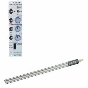
Doepfer A-198 TRC Trautonium Manual/Ribbon Controller Module (controller synth module)
Cat: 755418 Rel: 28 Nov 19
A-198 module with versatile ribbon controller
Notes: Module A-198 is a Trautonium Manual resp. Ribbon Controller. The controlling element of the A-198 is a linear position sensor (length about 50 cm) that has available a pressure sensor too.
Touching the sensor with a finger generates a control voltage CV1 that is proportional to the position of the finger. The scale (i.e. the relation between position difference and voltage difference) is adjustable with a potentiometer at the front panel. A hold switch is used to determine if the CV voltage is held after removing the finger (hold = on) or if the CV voltage jumps to 0V (hold = off). In the last case (hold = off) a gate signal is derived from the CV voltage whenever a finger touches the sensor (e.g. for triggering an envelope generator).
A sensitive pressure sensor located below the position sensor generates a second control voltage CV2 that increases with higher pressure of the finger. Even for CV2 the scale is adjustable. A second gate signal is triggered as soon as the pressure exceeds a certain value. The gate threshold is adjustable at the front panel.
The sensors are located in a separate metal frame (length about 600 mm, width about 30 mm, height about 18 mm, weight: about 900 g, colour: silver-grey). The connection between the module and the sensor frame is made by a 4 pin cable (same as used for USB connections).
Typical applications:
- Trautonium manual, the string is replaced by the position sensor that is much easier to use and cheaper than the string. In combination with the Subharmonic Oscillator A-113, the Trautonium Filter A-104 and some auxiliary modules a complete Trautonium replica may be realized. In combination with the Quantizer A-156 exact semitone intervals are possible.
- Ribbon Controller for any A-100 parameter
… Read moreTouching the sensor with a finger generates a control voltage CV1 that is proportional to the position of the finger. The scale (i.e. the relation between position difference and voltage difference) is adjustable with a potentiometer at the front panel. A hold switch is used to determine if the CV voltage is held after removing the finger (hold = on) or if the CV voltage jumps to 0V (hold = off). In the last case (hold = off) a gate signal is derived from the CV voltage whenever a finger touches the sensor (e.g. for triggering an envelope generator).
A sensitive pressure sensor located below the position sensor generates a second control voltage CV2 that increases with higher pressure of the finger. Even for CV2 the scale is adjustable. A second gate signal is triggered as soon as the pressure exceeds a certain value. The gate threshold is adjustable at the front panel.
The sensors are located in a separate metal frame (length about 600 mm, width about 30 mm, height about 18 mm, weight: about 900 g, colour: silver-grey). The connection between the module and the sensor frame is made by a 4 pin cable (same as used for USB connections).
Typical applications:
- Trautonium manual, the string is replaced by the position sensor that is much easier to use and cheaper than the string. In combination with the Subharmonic Oscillator A-113, the Trautonium Filter A-104 and some auxiliary modules a complete Trautonium replica may be realized. In combination with the Quantizer A-156 exact semitone intervals are possible.
- Ribbon Controller for any A-100 parameter
1 in stock $222.56
Items 1 to 4 of 4 on page 1 of 1