
 USD
USD


Filter

Coming Soon
Equipment
Format
Brand
Featured
Price
Tags
When function Direct (Direction) is selected these running modes are available:
Up
Down
2 x Up (each step is played twice with the normal tempo, not to be confused with Ratcheting x2, see below)
2 x Down (each step is played twice with the normal tempo, not to be confused with Ratcheting x2, see below)
Pendulum type 1 (start and end step are played twice)
2 x Pendulum type 1 (each step is played twice with the normal tempo, start and end step are played 4x)
Pendulum type 2 (start and end step are played once)
Random (Rnd)
When function Preset is selected the illuminated buttons are used to call up one of the 8 presets. In each preset these parameters are stored: active steps, running direction, length of the sequence, ratcheting. To call up one of the 8 stored presets one has to push and hold the button Function and then operate short-time one of the buttons 1 - 8 while the toggle switch Program is in position Preset. To store the present paramaters in one of the 8 presets the procedure is similar but one has to operate one of the buttons 1 - 8 for a longer time (approx 3 seconds).
Depending on the position of the Program toggle switch the Ratcheting button is used to program the ratcheting feature (x2, x3, x4) individually for each step of the sequence (toggle switch Program in position Rx2, Rx3 or Rx4). In case that at the step in question another ratcheting is already programmed (eg x2 or x3 when x4 is chosen) the other ratcheting is overwritten (kind of radio button function between the ratchetings x2, x3 and x4). Details about the ratcheting function are explained at the module A-160-5.
The button Start/Stop is used to start or stop the sequence manually. Button Reset sets the sequence to the first step. For this also the external input Reset can be used.
The module does not feature built in clock generator. Rather an external Clock signal is used. The positive edge of the incoming clock signal triggers the advance of the sequence to the next step.
The voltage range of the control voltage generated by the module can be switched to 3 different ranges by the toggle switch Range: 0 - +1V / 0 - +2V / 0 - +4V. The control voltage is available at socket CV. The voltage is not quantized. But there is an internal pin header available that outputs the data via Midi (note on/off from Midi note 36. Midi channel 1). It can be used to control a MIDI-to-CV interface if quantized control voltages are required, eg the planned Micro-CV-Interface A-190-9)
The Gate signal appears at socket Gate. The pulsewidth of the gate signal is defined by the pulsewidth of the clock signal provided that ratcheting is not active at the step in question.
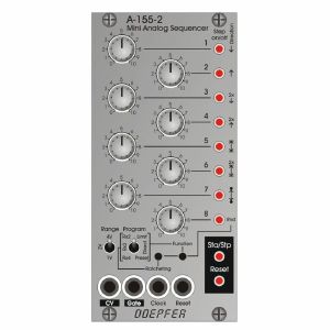
Controls and displays:
1 - 8 (rotary controls): manual adjustment of the control voltage for each step
1 - 8 (illuminated momentary switches/buttons): manual gate setting for each step, also used for special functions in combination with other controls (setting of first/last step, running direction, ratcheting)
Range: toggle switch for selection of the control voltage range
Program: toggle switch for selection of a function in combination with the buttons Ratcheting and Function
Ratcheting: button for the programming of ratcheting in combination with the toggle switch Program
Function: button for the programming of sequence length (Limit) and running direction (Direct) as well as for the Preset management (Preset)
Sta/Stp: button for the manual control of Start and Stop, in running state the LED of this button displays the state of the Gate output (ie it flashes in the rhythm of the Gate output)
Reset : manual reset button
CV : control voltage output
Gate : gate output
Clock: clock input, the pulsewidth of the clocjk signal defines the pulsewidth gate signal
Reset: reset control input, reset type selectable via internal jumpers (eg positive edge triggers the jump to first step/positive leveltriggers the jump to first step and remains at first step as long as the reset input is high/waiting for the next positive edge of the clock signals before reset is carried out)
This product is available for pre-order at Juno, for shipping on the release date. You won’t be charged until the order is despatched.
We'll keep you informed of your order at every stage, and let you know if the release date changes.
If the price of the item drops before it's released, you will pay the lower price, but if it increases, you'll only pay the price you see today.
If you also include in-stock items on your order, they’ll be charged and shipped within 24 hours as usual.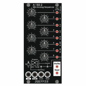
When function Direct (Direction) is selected these running modes are available:
Up
Down
2 x Up (each step is played twice with the normal tempo, not to be confused with Ratcheting x2, see below)
2 x Down (each step is played twice with the normal tempo, not to be confused with Ratcheting x2, see below)
Pendulum type 1 (start and end step are played twice)
2 x Pendulum type 1 (each step is played twice with the normal tempo, start and end step are played 4x)
Pendulum type 2 (start and end step are played once)
Random (Rnd)
When function Preset is selected the illuminated buttons are used to call up one of the 8 presets. In each preset these parameters are stored: active steps, running direction, length of the sequence, ratcheting. To call up one of the 8 stored presets one has to push and hold the button Function and then operate short-time one of the buttons 1 - 8 while the toggle switch Program is in position Preset. To store the present paramaters in one of the 8 presets the procedure is similar but one has to operate one of the buttons 1 - 8 for a longer time (approx 3 seconds).
Depending on the position of the Program toggle switch the Ratcheting button is used to program the ratcheting feature (x2, x3, x4) individually for each step of the sequence (toggle switch Program in position Rx2, Rx3 or Rx4). In case that at the step in question another ratcheting is already programmed (eg x2 or x3 when x4 is chosen) the other ratcheting is overwritten (kind of radio button function between the ratchetings x2, x3 and x4). Details about the ratcheting function are explained at the module A-160-5.
The button Start/Stop is used to start or stop the sequence manually. Button Reset sets the sequence to the first step. For this also the external input Reset can be used.
The module does not feature built in clock generator. Rather an external Clock signal is used. The positive edge of the incoming clock signal triggers the advance of the sequence to the next step.
The voltage range of the control voltage generated by the module can be switched to 3 different ranges by the toggle switch Range: 0 - +1V / 0 - +2V / 0 - +4V. The control voltage is available at socket CV. The voltage is not quantized. But there is an internal pin header available that outputs the data via Midi (note on/off from Midi note 36. Midi channel 1). It can be used to control a MIDI-to-CV interface if quantized control voltages are required, eg the planned Micro-CV-Interface A-190-9)
The Gate signal appears at socket Gate. The pulsewidth of the gate signal is defined by the pulsewidth of the clock signal provided that ratcheting is not active at the step in question.
Controls and displays:
1 - 8 (rotary controls): manual adjustment of the control voltage for each step
1 - 8 (illuminated momentary switches/buttons): manual gate setting for each step, also used for special functions in combination with other controls (setting of first/last step, running direction, ratcheting)
Range: toggle switch for selection of the control voltage range
Program: toggle switch for selection of a function in combination with the buttons Ratcheting and Function
Ratcheting: button for the programming of ratcheting in combination with the toggle switch Program
Function: button for the programming of sequence length (Limit) and running direction (Direct) as well as for the Preset management (Preset)
Sta/Stp: button for the manual control of Start and Stop, in running state the LED of this button displays the state of the Gate output (ie it flashes in the rhythm of the Gate output)
Reset : manual reset button
CV : control voltage output
Gate : gate output
Clock: clock input, the pulsewidth of the clocjk signal defines the pulsewidth gate signal
Reset: reset control input, reset type selectable via internal jumpers (eg positive edge triggers the jump to first step/positive leveltriggers the jump to first step and remains at first step as long as the reset input is high/waiting for the next positive edge of the clock signals before reset is carried out)
This product is available for pre-order at Juno, for shipping on the release date. You won’t be charged until the order is despatched.
We'll keep you informed of your order at every stage, and let you know if the release date changes.
If the price of the item drops before it's released, you will pay the lower price, but if it increases, you'll only pay the price you see today.
If you also include in-stock items on your order, they’ll be charged and shipped within 24 hours as usual.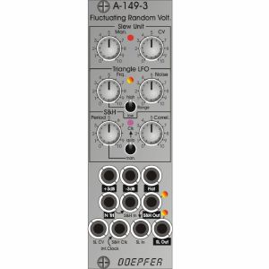
Module A-149-3 is based on the homonymous "Fluctuating Random Voltages" by Buchla. Compared to the historic original, a lot of functions have been added. For example the user has access to virtually all internal signals (e.g. Noisy Triangle or S&H) and there are a lot of adjustable parameters which were fixed in the original.
For example, the frequency and noisiness of the internal triangle oscillator, the correlation of the S&H and manual or automatic frequency control of the S&H clock oscillator. The fixed internal connections of the original are wired to sockets in the A-149-3 and can be used also individually as the connections of the original are realized as normalled sockets. That way e.g. the S&H or slew unit can be used independent from the other units.
The functions in detail:
As in the original a digital noise signal is filtered in three different ways. The three "noise flavours" are available at three sockets and can be used for all kind of noise applications:
+3db (+3dB per octave, a bright noise, also called blue noise)
-3dB (-3dB per octave, a dark noise, also called red or brown noise, Allan Strange calls it "reciprocal white noise")
Flat (flat spectrum, also called pink noise)
In the original the -3dB output is used add some noise to an internal triangle oscillator with fixed frequency (~ 100 Hz) and fixed "noisiness". The result is called "noisy triangle". In the A-149-3 the frequency of the triangle oscillator and the level of the noisiness can be adjusted. The frequency is adusted by means of the Frq. control and the Range switch (~ 110Hz ... 5 seconds period in position high). In addition one can select between the -3dB and Flat output as noisiness source by means of an internal jumper. When Noisiness control is fully CCW one obtains a clean undisturbed triangle signal. With Noisiness control fully CW the result is a triangle signal with a lot of noise or randomness. The noisy triangle signal is available at the socket "N Tri" and is displayed with a dual colour LED.
The "N Tri" signal is normalled to the signal input of the subsequent Sample&Hold unit (S&H). The clock signal for the S&H is generated by an internal rectangle oscillator. This signal is normalled to the S&H clock socket and is displayed by an LED. One can select between manual and automatic control of the clock period by means of a toggle switch. In position "man." the period is controlled manually by the "Period" control. With control "Period" fully CCW one obtains the shortest period or highest frequency. Turning the control up increases the period or lowers the frequency. In position "auto" of the switch the period is controlled by the slew unit.
In this position a vactrol is used to define the frequency of the S&H clock. This vactrol is controlled in the same way as the vactrols of the slew unit, i.e. the period of the S&H clock changes simultaneously with the slew time. In the historic original only the auto mode was available. There was no manual control available.
The S&H has another special feature: the Correllation control. It's a feedback function where shares of the S&H output are fed back to the S&H signal input and mixed with the actual S&H input signal. The result is slurring the signal like a sub-audio lowpass filter, kind of a "digital slew function" because the gradation of the signal persists.
The S&H output is availabe at the corresponding socket and is displayed with a dual colour LED.
The S&H output is normalled to the signal input of the subsequent Slew Limiter unit (SL). The core of the slew limiter are two vactrols (vactrol = combination of a light emitting diode/LED and a light dependent resistor/LDR built into lightproof case). The brightness of the vactrol LEDs can be controlled manually (control "Man." of the slew unit) and by an external control voltage (socket "SL CV" with associated attenuator "CV" of the slew unit). The brightness of the vactrol LEDs is displayed at the top of the front planel. As already mentioned a third vactrol can be used to control the frequency of the S&H clock oscillator simultaneously to the slew limiter. The SL output is availabe at the corresponding socket and is displayed with a dual colour LED.
Due to the access facilities to many of the internal signals and connections it's possible to use the sub-units also for other applications. E.g. the noisy triangle signal, the S&H unit (incl. correlation) or the SL unit can be used for other signals. The S&H clock can be applied also from outside to synchronize the S&H to other signals.
If required, the internal clock signal is available at a pin header of the pc board.
Controls, Switches and Displays:
Slew Unit
Man.: manual adjustment of the slew time
CV: attenuator for the SL CV input
LED: display of the slew function (bright = short slew lime, dark = long slew time), identical to the brightmess of the vactrol LEDs
Triangle LFO
Frq.: LFO frequency, range ~ 110 Hz ... 5 seconds period
Noise: adjustment of noisiness (= perturbance of the triangle signal)
+3dB/-3dB: switch for the source of noisiness
LED: display of the noisy triangle signal, dual color LED (rot = positive / yellow = negative output voltage)
Sample&Hold (S&H)
Period: period of the internal clock signal for the S&H unit, fully CCW = shortest period or highest frequency, fully CW = longest period or lowest frequency
LED: display of the internal clock signal
Correl.: adjustment of the correllation of the S&H unit
Man./Auto: switching between manual and automatic control of the clock frequency, when auto is selected the clock frequency is controlled by the slew unit
LED: display of S&H output, dual color LED (rot = positive / yellow = negative output voltage)
Slew Limiter (SL)
LED: display of SK output, dual color LED (rot = positive / yellow = negative output voltage)
Sockets:
+3dB : filtered digital noise with +3dB per octave (output)
-3dB : filtered digital noise with -3dB per octave (output)
Flat : flat noise output
N Tri : Noisy Triangle output, about 10Vpp (-5V ... +5V)
S&H In: S&H signal input, normalled to N Tri
S&H Out : S&H signal output
SL CV: control voltage of the slew limiter unit, connected to the corresponding attenuator "CV" of the slew unit
S&H Clk: clock input of the S&H unit, normalled to the internal clock oscillator
SL In: slew limiter input, normalled to S&H Out
SL Out : slew limiter output
The arrow symbols indicate the normalling of sockets. Outputs are inverse labelled.
Technical details:
Frequency range of the triangle LFO: about 110 Hz ... 5 seconds period
Output level of the triangle LFO: ~ 10 Vss (-5 V...+5 V)
Frequency range of the internal clock oscillator: about 3 seconds ... 30Hz
Output level of the internal clock oscillator: ~ 10 Vss (0 V...+10 V)
Required input level of the S&H clock input: +5V
Depth: 45mm
8 HP
This product is available for pre-order at Juno, for shipping on the release date. You won’t be charged until the order is despatched.
We'll keep you informed of your order at every stage, and let you know if the release date changes.
If the price of the item drops before it's released, you will pay the lower price, but if it increases, you'll only pay the price you see today.
If you also include in-stock items on your order, they’ll be charged and shipped within 24 hours as usual.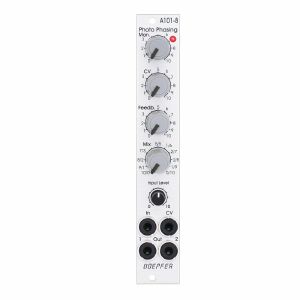
The module has these controls and in/outputs available:
Control Man. : manual control of the phase shift offset (base value)
Control CV: attenuator for the signal applied to the CV socket
Control Feedb.: Feedback or Resonance (similar function as filter resonance/feedback/emphasis)
Control Mix: sets the mixing ratio between original and phase shift signal appearing at output 1
fully CCW: only the modified input signal appears at output 1 (see note below *)
center: a mixture between the modified input signal and the phase shift signal appears at output 1, that's the standard position for the classical phasing effect
fully CW: the pure phase shifted signal appears at output 1 (e.g. for vibrato effects)
Control Input Level: attenuator for signal applied to the In socket
Socket In: audio input
Socket CV: control voltage input
Socket Out 1: audio output 1 (mix signal)
Socket Out 2: audio output 2 (modified input signal)
LED: visual control of the phase shift
The module has some peculiarities (same as the historic model):
The input signal is processed at first by a pre-stage which outputs a "modified" input signal (*). This signal is not processed by the phase shift stages but is affected by the feedback setting. Only when feedback is set to zero this signal is identical to the input signal. Otherwise it contains feedback components.
This signal is output on socket Out 2.
When both output sockets Out 1 and Out 2 are used as stereo channels one obtains a spatial stereo sound effect.
The same signals is also used for the CCW position of the mix control. With mix control fully CCW the unmodified signal appears only if the feedback control is set to zero. Otherwise it contains feedback components.
The historic model had two audio inputs: one 5-pin DIN socket and a 1/4" jack socket. The DIN socket was intended for high-level line signals. When the 1/4" jack socket was used the amplification of the pre-stage increased by about 100. The 1/4" jack socket was intended for low level signals (e.g. electric guitars or microphones). For this feature the A-101-8 has an internal jumper that can be used to increase the amplification. As long as the module is used within the A-100 system usually the lower amplification is used to avoid distortion.
The 8 photo resistors and LEDs are assembled within an small lighproof box. In addition the pc boards are made of lighproof black material to avoid interfering light from other modules or the bus board.
Dimensions
4 HP
45 mm deep
Current Draw
30 mA +12V
30 mA -12V
2 in stock $111.61
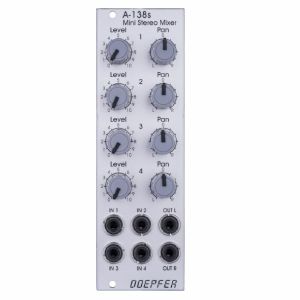
You may regard the A-138s as a smaller version of the A-138m Matrix Mixer.
Inputs and outputs are DC coupled, i.e. the module can be used for the mixing of control signals too.
- 3U Eurorack module, 8 HP wide, 30 mm in depth
- Power consumption: 10 mA at +12 V and 10 mA at -12 V
quote 671589
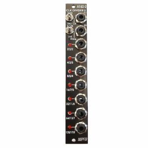
The Clock input will take any digital signal from, eg., an LFO, MIDI sync, or the gate from a MIDI-CV interface. At the outputs, you have access to three sets of seven different sub-divided clock signals, from half the clock frequency down to 1/128. The low/high levels of the output signals are 0V and about +10V.
The A-160-2V also has a reset input. Whenever a reset signal is sensed, all outputs are set to certain levels which depend upon the selected mode.
HP : 4
quote 864696
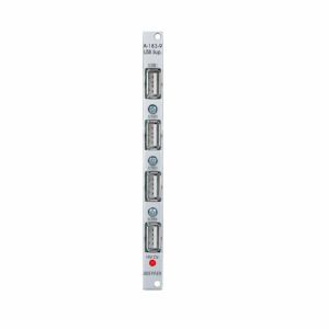
The module has no USB function but provides only the +5V supply for USB devices.
A control LED shows if the +5V are present.
Note: The module requires an A-100 case with built in power supply A-100PSU3. Only this A-100 supply has the required +5V available. We do not recommend the usage of an older A-100 case with A-100PSU2 as this would require the +5V adapter A-100AD5 and the max. current would be limited to 100mA.
quote 711015
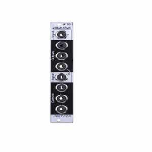
Application: copying/buffering of CV, gate and audio signals.
1 in stock $54.96
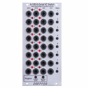
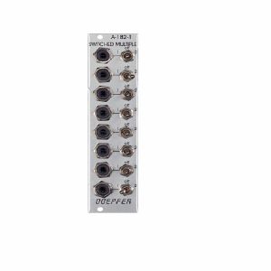
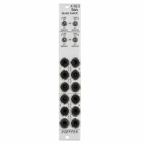
For each unit the operating mode can be selected: Toggle or Level controlled. In Toggle mode the rising edge of the CV input or operating the manual control button changes the state of the switch. In Level mode the switch state is defined by the voltage applied to the CV input (low voltage = I/O1, high voltage = I/O2) or by the state of the manual control button (not pressed = I/O1, pressed = I/O2). The modes are programmed very easily: Operating the Toggle/Level button of the program section displays the current state of each switch with the LEDs: left LED on = Toggle mode, right LED on = Level mode. Operating the manual control button of the switch in question changes the toggle/level mode while the Toggle/Level button of the program section is operated. During the programming patched CV signals may have to be removed as the CV signals would interfere with the manual operating buttons during the programming process.
In addition, it's possible to define master/slave groups. In such a group the upper unit (= master) controls also the state of the following switches provided that they are defined as slaves. Master/slave programming is also very simple: Operating the Master/Slave button of the program section displays the current state of each switch with the LEDs: left LED on = Master, right LED on = Slave.
When all 8 units are defined as master all switches are independent from each other. If for example the sequence is MSSSMSMS the control unit of the first switch also controls the switches 2, 3 and 4. The control unit of switch 5 also controls the switch 6, and the control unit of switch 7 also controls the switch 8. The current states of the slave switches are overwritten by the state of the master switch.
Technical note: To protect the electronic switches in case of an unsuitable patch (e.g. connection of two outputs) a 1k protection resistor is inserted into the O/I line of each switch. If control voltages used for VCOs are switched this may cause a small voltage drop and lead to undesired audible detuning. For this application we recommend to insert a CV buffer between A-150-8 and the VCO(s), e.g. the Buffered Multiple A-180-3 or the Precision Adder A-185-2. Integrating the buffers into the module A-150-8 was not possible because this would ruin the bidirectionality of the switches.
Width: 12 HP / 60.6 mm
Depth: 55 mm (measured from the rear side of the front panel)
Current: +40mA (+12V) / -5mA (-12V)
1 in stock $172.70
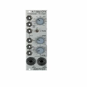
Crossfader: With the crossfading control CF you blend manually between the inputs In 1 and In 2. The Mute switch allows for muting one of the two signals, independent on the crossfader position.
Effect insert: The signal at input In1 is emitted at the FX Send output and can be attenuated with the Atten. control because the modular system works with much higher levels.
The effect unit's output is inserted to the FX Return input socket and its level can be boosted with the Amp. control. The processed signal is available at the bottom in 2 socket.
Use the CF control to blend between the original signal and the effect signal and to mute switch for quick muting e.g. of the effect return signal.
1 in stock $74.86
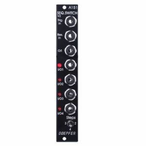
It includes trigger and reset inputs, four in/outputs, and a common out/input. Each time a pulse is received at the trigger input socket, the common out/input is connected to the next in/output. After the fourth in/output, the next trigger makes it step back to the first again, and so on. A positive pulse at the reset input switches the out/input immediately back to the first in/output. Voltages in the range -8V...+8V at the O/I resp. I/O sockets can be processed by the module.
Four LED's indicate the active in/output (ie. the one that is connected to the out/input at any particular time).
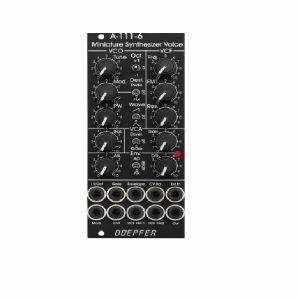
- Tune: manual tune control (with an internal jumper the range can be set to ~ +/-1 half an octave or ~ +/-2.5 octaves)
- Oct: range switch -1 / 0 / +1 octave
- Mod: modulation depth (attenuator wired to the Mod. socket)
- Dest: switch that is used to address the modulation to frequency modulation (position FM) or pulsewidth modulation (positon PM), in centre positon no modulation
- PW: manual pulsewidth control for rectangle waveform, PW can be also modulated by the Mod. input as mentioned above
- Wave: waveform switch (sawtooth / off / triangle), the sum of the waveform chosen by this switch and the rectangle is fed into the VCF (to turn the rectangle off the PW control has to be set fully CCW or fully CW)
- 1V/Oct. (socket): external CV input for VCO frequency (1V/octave)
- Access to internal bus CV (via jumper, optional, please remove the bus jumper if this feature is not used to avoid unwanted frequency modulation as then the unused CV line of the bus works as a kind of antenna)
- Triangle core VCO, frequency range about 32Hz ... 8kHz
Balance unit:
- The balance unit is made of two VCAs which are controlled by the sum of manual Balance control and the balance CV input in the opposite direction.
- The audio input of VCA1 is hard-wired to the VCO output, audio input 2 is connected to the socket Ext.In.
- The output of the balance unit is used as audio input for the VCF
- Bal.: manual balance control, fully CCW the internal VCO is used, fully CW the external signal (Ext.In) is used, at centre position both signals have about the same level
- CV Bal.: CV input for balance (range about 0...+5V)
- Ext. In: external audio input for VCA2, about 5 Vpp level required for similar loudness as the internal VCO
- This socket is normalled to the internal VCO suboctave f/2 signal (rectangle with half the frequency), if no external signal is applied the suboctave signal is used as the second signal for the balance unit
VCF:
- 24 dB low pass
- Frq: manual frequency control
- FM1: frequency modulation depth (attenuator wired to the VCF FM1 socket, the socket is normalled to the internal Envelope signal and then FM1 controls the modulation depth of the internal envelope applied to the filter)
- FM2 (socket) : second CV input for VCF without attenuator (about 1V/octave), can be used e.g. for VCF tracking by connecting the same CV which is used also for the VCO frequency
- Res: manual resonance control (up to self oscillation)
- If the VCO is turned off (waveform switch = centre position, pulsewidth control = fully CCW or CW) and the VCF resonance is set to maximum the module can be used as a sine oscillator, the tracking at socket VCF FM2 is about 1V/octave (not as precise as the VCO but much better than most other filters)
- ~ 11 octaves frequency range (~ 10 Hz ... 20kHz)
VCA:
- Gain: manual amplitude control (initial gain), can be used to open the VCA without envelope signal
- VCA (switch): used to switch between gate and envelope as control signal for the VCA, in centre position the VCA is not controlled by envelope or gate
- Note: when gate is used the VCA is controlled directly by the gate signal (i.e. hard on/off), this may lead to clicking noise under certain conditions (especially with low VCO/VCF frequencies)
- Special control scale: exponential scale in the range from about -20dB to -80/90dB, linear scale from about -20dB to 0dB
- Remark: this special control scale results in a loudness behaviour that is a bit different from pure linear or exponential VCAs
- Out: audio output of the module (= VCA output)
Envelope:
- Gate (socket): Gate input (min. +5V), can be normalled to the bus gate signal by means of a jumper
- Att: manual control for Attack
- D/R: manual control for Decay/Release
- Env. (switch): used to switch between A/D, ADSR and A/R mode of the envelope generator, in centre position (ADSR) the sustain level is fixed to about 50%
- Envelope (socket): envelope output (about +10V)
- CVT (socket): CV input for time control, by means of two internal jumpers one can select which time parameters are controlled by the CVT input (e.g. A only or D/R only or A/D/R) and in which direction (i.e. if an increasing CVT shortens or stretches the time parameter in question)
- Envelope LED display
- Attack time range: ~ 1ms ... 5 sec (can be extended by using the CVT input)
- Decay/Release time range: ~ 1ms ... 15 sec (can be extended by using the CVT input)
Examples:
- All switches in left position or all switches in right position: 8-fold multiple
- Four switches in left position and four switches in right position: two 4-fold multiple
- X switches in left position, Y switches in right position and Z switches in centre position: two separate multiples with some sockets turned off
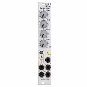
The module generates the signals white noise, colored noise, continuous random voltage and stepped random voltage (derived from the continuous random voltage by means of a S&H/T&H unit).
The noise signal is generated 100% analog by amplification of the noise of a transistor. White and colored noise are usually used as audio sources. The random voltages are normally used as control voltages (e.g. for filter frequency or any other voltage controlled parameter).
The A-118-2 gives you the ability to mix the relative amounts of Red (low frequency component) and Blue noise (high frequency component) in the colored noise output.
For the continuous random voltage the rate of change (Rate) and amplitude (Level) of the random voltage can be adjusted. The continuous random voltage is derived from the colored noise signal by low pass filtering. Consequently the settings of the controls for the colored noise (Blue, Red) affect the behavior of the random voltage! A dual color LED (red = positive / yellow = negative output voltage) indicates the continuous random voltage.
The continuous random voltage is used as source for the S&H/T&H unit. The type of operation can be set to S&H (sample and hold) or T&H (track and hold). When T&H is chosen the output signal follows the input signal (= continuous random voltage) as long as the Clock input is "high". As soon as the clock signal changes to "low" the last voltage is stored. When S&H is chosen the input signal (= continuous random voltage) is sampled at the rising edge of the Clock signal.
For the Clock signal a "digital" signal (e.g. Clock, Gate, rectangle output of an LFO) is required. It does not work with slowly changing continuous CV signals. Another dual color LED (red = positive / yellow = negative output voltage) indicates the stepped random voltage.
Controls:
Blue: share of the high frequencies in the the colored noise output
Red: share of the low frequencies in the the colored noise output
Rate: rate of change of the continuous random voltage
Level: amplitude of the continuous random voltage
TH/SH: switches between T&H and S&H
Inputs and outputs:
RND: continuous random voltage output (with LED display)
TH/SH: stepped random voltage output (with LED display)
Clk: Clock input of the S&H/T&H unit
C Noise: colored noise output
W Noise: white noise output
Important notes:
After power on it takes a few minutes until the two noise signals and the random signals are generated. The module is not faulty when after power on the signals do not appear immediately!
The S&H/T&H function is realized by pure analog circuitry (electronic switch followed by a holding capacitor and buffer). Consequently the output voltage drifts a bit in the holding state because the capacitor is discharged by parasitic resistors. The drift depends also upon environmental conditions like humidity or temperature.
Dimensions
4 HP
40 mm deep
Current Draw
20 mA +12V
20 mA -12V
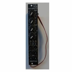
The module is composed of two identical voltage controlled amplifiers (VCA). Each VCA has a manual gain control (also named Initial Gain) and a control voltage input with attenuator. The character of the control scale can be switched to linear or exponential. All inputs and outputs are DC coupled. Consequently the VCAs can be used to process both audio and control voltages (e.g. for voltage control of the level of LFO or envelope signals). The signal input has no attenuator available but is capable to process up to 16Vpp signals (i.e. -8V...+8V) without distortion. For the processing of higher levels an external attenuator (e.g. A-183-1) is recommended.
The amplification range is 0...1. Even with a higher external control voltage the amplification remains at 1 (kind of "amplification clipping" at 1).
Controls (for each of both units):
- Gain: manual gain control (Initial Gain) in the range 0...1
- CV: attenuator for the CV input
- Lin/Exp: switches the VCA characteristic to linear or exponential, in center position the VCA is off (mute function)
Inputs and outputs (for each of both units):
- CV: control voltage input, min. +5V required for max. amplification (1) with CV control fully CW and Gain fully CCW
- In: signal input, max. 16Vpp (+8V...-8V) without distortion
- Out: signal output
quote 731940
The module can be treated as a slimmed version of the quad LFO A-143-3 as it has similar features available. But the distances between the controls are smaller and rubberized small-sized knobs are used. In return the front panel has 4 HP only which is less than one third of the A-143-3. The module is primarily planned for applications where only limited space is available. The functional difference compared to the A-143-3 are the missing sawtooth outputs and frequency range switches.
! low stock $77.49

The amplification range is 0...1. Even with a higher external control voltage the amplification remains at 1 (kind of "amplification clipping" at 1).
Controls (for each of both units):
Gain: manual gain control (Initial Gain) in the range 0...1
CV: attenuator for the CV input
lin/exp: switches the VCA characteristic to linear or exponential, in center position the VCA is off (mute function)
Inputs and outputs (for each of both units):
CV: control voltage input, min. +5V required for max. amplification (1) with CV control fully CW and Gain fully CCW
In: signal input, max. 16Vpp (+8V...-8V) without distortion
Out: signal output
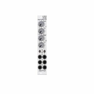
A-130-2v is the slim version of module A-132-3 and offers essentially the same features. But the distances between the controls are smaller and rubberized small-sized knobs are used. In return the front panel has 4 HP only which is half the width of the A-132-3. The module is primarily planned for applications where only limited space is available.
Power consumption: 30mA at +12V and 30mA at -12V
Depth: 50mm
HP : 4
quote 973749
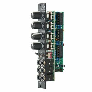
The signal inputs are able to process levels up to about 20Vpp without clipping (20Vpp = 20V peak-to-peak or about -10V...+10V) . Each CV input is equipped with a trimming potentiometer that is used to adjust the sensitivity of the CV input in question. In the factory the module is adjusted for the CV range 0...+5V but can be re-adjusted by the user for other control voltage ranges (e.g. 0...+10V).
The amplification range for each single VCA is 0...1. The signals of the sum outputs have a lower amplification to avoid distortion at the sum outputs.
The VCAs and mixers are fully DC coupled, i.e. the module can be used for the processing of both audio and control voltage signals. The control voltage and signal inputs can be normalled by means of small solder pads (e.g. 1 > 2 > 3 > 4 and so on, or 1 > 5, 2 > 6, 3 > 7, 4 > 8 for the stereo application mentioned below).
Typical applications
any kind of VCA application (e.g. voltage controlled attenuation of audio or control voltage signals)
two voltage controlled mixers with four channels each
voltage controlled stereo mixer with four channels each, for this the control voltage inputs have to be correspondingly patched or internally normalled: CV1=CV5 /CV 2=CV6 / CV3=CV7 / CV4=CV8
voltage controlled mixer with eight channels
add-on for the Joystick module A-174-4
Technical notes
The following document shows the positions and functions of the jumpers and trimming potentiometers of the module: A130_8_trimming_potentiometers_and_jumpers.pdf
When the trimming potentiometer in question is moved CCW (counterclockwise) the sensitivity of the CV input in question increases (view to the top edge of the module).
Trimming procedure: apply the max. CV voltage that will occur in your application (e.g. +8V) to the CV input and a constant audio signal to the audio input (e.g. a VCO sawtooth). Then adjust the trimming potentiometer in question until the max. output level is reached and does not become higher even if the trimming potentiometer is turned further. Possible the the trimming potentiometer has to be turned back again a bit to find the correct position.
With the trimming potentiometer adjusted to max. sensitivity the linear amplification starts at about +0.1 control voltage (CV). We introduced this small dead range of about 100 mV to make sure that the VCA fully closes with CV = 0V.
It's possible to change the amplifications of the internal mixers used for the sum outputs (1-4, 1-8, 5-8) also to 1. Pay attention that then clipping/distortion may occur at the sum outputs. For this the 22k resistors R41 (Sum 1-4), R44 (Sum 5-8) und R51 (Sum 1-8) have to be replaced by 47k. As they are smd resistors sufficient experience with soldering/desoldering of smd parts is essential. And we have to point out that warranty is void if such modifications are carried out by the customer. The positions of the resistors are shown in the document A130_8_trimming_potentiometers_and_jumpers.pdf.
If multiple exponential VCAs are required module A-132-4 is recommended.
Width: 6 HP / 30.1 mm
Depth: 40 mm (measured from the rear side of the front panel)
Current: +50 mA (+12V) / -50 mA (-12V)
1 in stock $114.37
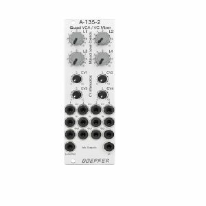
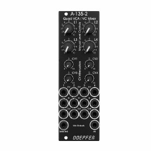
Controls, In/Outputs and Functions of each VCA:
- Level (manual control of the VCA amplification), small rubberized knob (L1...L4)
- Control voltage input with associated attenuator (CV1...CV4), for the full VCA control range about 0...+5V control voltage are required (attenuator fully clockwise), for higher control voltages the attenuator is used, the attenuators are without knobs, just plastic shafts with white marker
- Signal Input
- Signal Output
- All inputs and outputs are DC coupled. Consequently the VCAs can be used to process both audio and control voltages (e.g. to control the level of LFOs or envelopes)
- The signal input is not equipped with an attenuator. But the VCAs can process all signals up to 15Vpp / -7.5...+7.5V without clipping. In case of higher levels an external attenuator is required (e.g. A-183-1).
- The available amplification range is 0...1, the maximal amplification is 1 (i.e. it "clips" and remains at 1 even if the control voltage goes beyond the value that corresponds to amplification 1)
Functions of the voltage controlled mixers:
- Two outputs ("Selected" and "All")
- Selected output: the ouput if a VCA is removed from this sum signal when a plug is inserted into the corresponding VCA output.
- All output: sum of all VCA outputs, regardless of inserted plugs into the VCA outputs
- The maximal amplification is about 0.6 to avoid clipping at the mixer outputs (otherwise the outputs may distort with 15Vpp signals at each signal input and full amplifications)
Special functions of the voltage controlled mixers (selectable by internal jumpers):
- Dual Stereo VCA: In this case the control unit of VCA1 (L1 + CV1) affects also VCA3 and the control unit of VCA2 (L2 + CV2) affects also VCA4, the control units of VCA2 and VCA4 are out of operation
- Quad VCA: In this case the control unit of VCA1 (L1 + CV1) affects all four VCAs. The control units of VCA2, VCA3 and VCA4 are out of operation. In this mode the module has the same function as module A-132-2. That's why module A-132-2 will be discontinued.
- Normalling of the signal inputs: by means of internal jumpers signal input 1 can be normalled to signal input 2, signal input 2 to signal input 3 and signal input 3 to signal input In 4. That way the same input signal can be distributed to four different channels by means of control voltages (e.g. quadrophonic distribution of audio signals). Suitable control voltage sources are e.g. A-144 (Morphing Controller) or A-143-9 (Quadrature LFO).
1 in stock $133.02
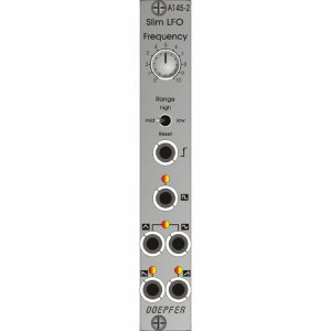
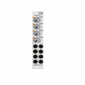
Five waveforms are available: sawtooth, inverted sawtooth, triangle, sine and square wave. The LFO can be used as a modulation source for any number of modules - for instance modulating the pulse width or frequency of a VCO, modulation of the cut-off frequency of a VCF, or amplitude modulation with a VCA.
A three-way switch lets you select three frequency ranges, spanning from one cycle every several minutes at the lowest, to moderate audio frequency at the highest (about 4-5 kHz).
The LFO signal can also be synchronised, via the reset input.
Identical to the A-145-1, but only 4 HP wide and with additional LEDs for the square wave and the sawtooth signal.
Power consumption: 30mA at +12V and 20mA at -12V
Depth: 45mm
4 HP
quote 1081646

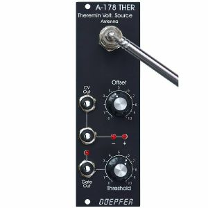
The distance range is about 30 cm. Additionally the module is equipped with a Gate output with adjustable threshold level. To simulate the original Theremin two A-178, a VCO (e.g. A-110) and a linear VCA (e.g. A-130 or A-132) are required. But of course the A-178 can be used to control other functions in the A-100 (e.g. filter frequency, modulation depth and/or speed, tempo, attack/decay time and so on).
The CV output voltage of the A-178 can range - according to the setting of the front panel controls - from -10V...+10V.
The gate output switches from 0V to about +10V.
Power consumption: 60mA at +12V and 20mA at -12V
Depth: 40mm
HP : 8
quote 852800
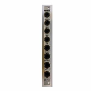
It adds two outputs from the Dome filter (+45 and -45 degrees) as well as separate outputs from the ring modulators 1 and 2, and from the internal envelope generator. Furthermore, it offers dedicated outputs for Up and Down Shift, allowing the module to be patched in stereo.
*Note: The expander can only be used in conjunction with the module A-126-2.
HP : 2
quote 852803
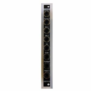
It adds two outputs from the Dome filter (+45 and -45 degrees) as well as separate outputs from the ring modulators 1 and 2, and from the internal envelope generator. Furthermore, it offers dedicated outputs for Up and Down Shift, allowing the module to be patched in stereo.
*Note: The expander can only be used in conjunction with the module A-126-2.
HP : 2
quote 852807
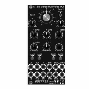
Controls:
F: master frequency control for both filters (large knob)
Type 1 / Type 2: filter type panning/morphing L-N-H-B
Link to 1: Toggle switch so that Type 1 also controls type of filter 2 (i.e. simultaneous filter type control for both filters)
SFM1 / SFM2: Single Frequency Modulation controls (polarizers), connected to the corresponding sockets SFM1/SFM2 (socket SFM1 is normalled to a fixed positive voltage, SFM2 is normalled to SFM1, that way the controls SFM1/SFM2 work as frequency controls for each filter provided that no modulation signals are patched to the SFM1/SFM2 sockets)
CFM: common frequency control, controls two VC-polarizers which process the signals connected to the two sockets CFM1/CFM2, CFM2 is normalled to CFM1, that way also the same modulation signal (e.g. an envelope generator) can be used for both filters and the level controlled simultaneously by the CFM control
Delta F: controls the difference between the frequencies of the two filters manually (frequency "spread"), at centre position the frequencies are the same
Delta FM: controls the level of the Delta FM signal (socket), which allows to control the spread between the frequencies also by an external control voltage (e.g. by an LFO or ADSR)
Q: controls the resonance of both filters simultaneously
Level 1 / Level 2: attenuators for the two audio inputs
QM/TM1, QM/TM2: attenuators for the modulation inputs QM/TM1 and QM/TM2
Sockets:
In1 / In2: audio inputs (In2 is normalled to In1)
Out1 / Out2: audio outputs
F: common frequency control input for both filters (~ 1V/oct)
Delta FM: Control voltage for frequency spread, processed by the polarizer Delta FM
SFM1 / SFM2: single frequency modulation inputs, processed by the polarizers SFM1 and SFM2, SFM1 is normalled to a fixed positive voltage, SFM2 is normalled to SFM1#
CFM1 / CFM2: common frequency modulation inputs, processed by the two voltage controlled polarizers controlled by CFM knob, CFM2 is normalled to CFM1
QM/TM1, QM/TM2: the addressing of these sockets/attenuators is defined by internal jumpers. QM means Q modulation (i.e. resonance modulation), TM means filter type modulation (QM1 = resonance modulation filter 1, QM2 = resonance modulation filter 2, TM1 = filter type modulation filter 1, TM2 = filter type modulation filter 2), socket QM/TM1 is normalled to a fixed positive voltage, QM/TM2 is normalled to QM/TM1
A 45 degrees triangle next to a socket means that the switching contact of the socket is normalled to a fixed positive voltage (SFM1, QM/TM1).
A vertical triangle indicates the normalling of two sockets (In1>In2, SFM1>SFM2, CFM1>CFM2, QM/TM1>QM/TM2).
If the filters do not behave as expected please pay attention to these peculiarities:
For the controls SFM1, SFM2, CFM, Delta F and Delta FM the centre position is the neutral position as these are polarizers. If the filter behaves unexpected these controls should be set to centre positions for the time being.
For the controls F, Q, Level 1, Level 2, QM/TM1 und QM/TM2 the fully CCW position is the neutral position as these are standard attenuators. If the filter behaves unexpected at least the controls QM/TM1 and QM/TM2 should be set to fully CCW. Via the normalling of the sockets QM/TM1 and QM/TM2 and the associated controls the filter parameters adjusted by the major controls (e.g. Type 1, Type 2 or Q) may be overwritten.
By means of small circles at the bottom right side of the front panel the user can mark the function of the QM/TM inputs. These assignments are possible:
QM/TM1 controls QM1, QM/TM2 controls QM2, the filter types are not controlled by external CVs
QM/TM1 controls TM1, QM/TM2 controls TM2, the resonances are not controlled by external CVs
QM/TM1 controls QM1 and QM2 simultaneously, QM/TM2 controls TM1 and TM2 simultaneously
1 in stock $249.13
The module has these controls and in/outputs available:
Control F : manual control of the frequency, for each LFO the frequency range can be selected by means of a jumper from two values (see technical notes)
frequency coverage of control F in the high frequency range: about 0.075 Hz (~ 13 seconds) ... 1,4kHz
frequency coverage of control F in the low frequency range: about 0.007 Hz (~ 140 seconds) ... 125Hz
Control CV: attenuator for the signal applied to the CV socket, by means of a jumper a small positive voltage can be applied to the switching contact of the /CV/ socket, as long as no patch cable is connected to /CV/ socket the CV control then works as fine control for the frequency
Switch CV Pol.: polarity switch for the signal applied to the socket /CV/
Control PW/PM: combined control for manual and CV control of the rectangle pulsewidth:
when no patch cable is connected to socket /P/ the control is used to adjust the pulsewidth (PW) manually
when a patch cable is connected to socket /P/ the control works as attenuator for the external CV signal with a basic pulsewidth of 50:50.
Socket /CV/: frequency control voltage input, in the factory the module is adjusted so that the sensitivity of this input is exactly 1V/octave when the CV control is fully CW.
Socket /R/: reset input, according to the associated jumper the reset input is edge triggered or level controlled (see technical notes for details)
Socket /P/: pulsewidth control voltage input
Sockets with waveform symbol: output of the waveform in question (triangle, sine, rising and falling sawtooth, rectangle)
The output voltage ranges are about -5V ... +5V (10Vpp), except the rectangle output
For the rectangle output one can choose by means of a jumper if the range is about -5V ... +5V or 0...+10V.
LED: visual control of the LFO (triangle)
The inputs of the module are labelled with white characters on black background (in the text included into two slashes). The outputs are labelled with black characters.
Technical notes and special features:
The basic frequency range of each LFO can be selected by means of a jumper. The settings correspond to two different capacitor values for the VCO circuit. The relation between the two ranges is about 1:11. When the upper range is selected frequencies from about 0.02 Hz up to 2.5kHz can be generated. For the lower range the values are about 0.0017 Hz ... 220Hz. To obtain these full frequency ranges external control voltages are required. With the frequency control F only the frequencies mentioned above are possible.
Apart from that the range for the manual control F can be reduced to obtain a finer resolutuion. For this a jumper has to be removed. The range of control F is then reduced to about 1:4.5 only.
In the factory the starting voltage of the triangle output after a reset is adjusted to 0V, i.e. the triangle starts from 0V with the rising slope after a reset. By means of a trimming potentiometer the starting voltage can be adjusted to another value (e.g. to -5V).
Another jumper is used to set the reset behaviour to edge triggered or level controlled. When set to edge triggered the rising edge of reset signal is used for the reset (independent of the duration of the "high" state of the reset signal). When set to level controlled the triangle output remains at the starting voltage as long as the reset signal is "high". Only when the reset signal turns "low" the triangle starts.
Dimensions
8 HP
45 mm deep
Current Draw
80 mA +12V
70 mA -12V
1 in stock $197.16
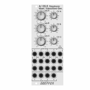
In addition the module features four frequency dividers which derive the suboctaves from the four input signals of channel A. The suboctave signals are wired to the switching contacts of the sockets of channel B. As long as the sockets of channel B are not patched the suboctave signals of channel A are used as inputs for channel B. The suboctaves are symmetrical rectangle waves with half the frequency of the corresponding signal A. For example two polyphonic VCOs A-111-4) can be used and patched to the channels A and C. Channel B then provides the suboctaves of channel A.
As the module is fully DC coupled it can be used also for the mixing of control voltages in a polyphonic environment (e.g. for envelopes, LFOs or other control voltages).
The switching contacts of the 12 input sockets and the four outputs are internally connected to pin headers. That way the module can be internally pre-patched to other polyphonic modules (e.g. the four inputs A to an A-111-4, the four inputs C to another A-111-4 and the outputs to the polyphonic filter A-105-4). As the switching contacts of the sockets are used for the internal pre-patching the internal patch can be overridden by using the sockets at the front panel.
The module has these controls and in/outputs available:
Controls Lev.A, Lev.B, Lev.C: manual level adjustment of the channels A, B and C
Controls CV A, CV B, CV C: attenuators for the corresponding control voltage inputs
Sockets A1...4: inputs channel A
Sockets B1...4: inputs channel B (if the sockets are not patched the suboctave signals are used for the inputs B)
Sockets C1...4: inputs channel C
Sockets CV A. CV B, CV C: control voltage inputs for the channels A, B and C
Sockets Out 1...4: outputs
Dimensions
10 HP
55 mm deep
quote 945421
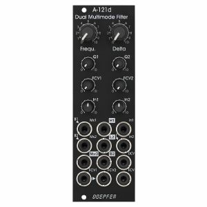
We attached great importance to the usability of the manual controls and CV inputs for dual filter applications: for the filter frequencies of both filters a common control (Frequ.) and a difference control (Delta, filter spread) are available. For both parameters even CV inputs are available (FCV, DCV). The resonance (Q1, Q2), the sensitivity of the individual frequency control input (FCV1, FCV2) and the level of the audio input (In1, In2) are adjusted by means of the individual controls for each filter.
The module has a simple audio mixing unit available with the inputs Mx1 and Mx2, and the output MxO. Provided that the mixer inputs are open bandpass 1 and bandpass 2 are normalised to the sockets Mx1 and Mx2. All other filter types are realized by connecting the other filter outputs (H1 = highpass 1, L2 = lowpass 2) to the mixer inputs.
Controls:
Frequ.: master frequency control for both filters
Delta: controls the difference between the frequencies of the two filters manually (frequency spread), at centre position the frequencies are about the same
Q1 / Q2: resonance controls for filter 1 and 2
FCV1 / FCV2: attenuators for the individual frequency control inputs FCV1 (filter 1) and FCV2 (filter 2)
In 1 / In 2: attenuators for the audio inputs of filter 1 and 2
Sockets:
Mx1 / Mx2: audio inputs of the mixer, Mx1 is normalised to bandpass 1 (B1), Mx2 is normalised to bandpass 2 (B2)
MxO: audio output of the mixer
In1 / In2: audio input of filter 1 and 2 (In2 is normalised to In1)
H1: highpass output filter 1
L2: lowpass output filter 2
B2: bandpass output filter 2
DCV: control voltage input for frequency spread (Delta)
FCV1 / FCV2: individual frequency control inputs, processed by the attenuators FCV1 and FCV2, socket FCV2 is normalised to socket FCV1
FCV: common frequency control input for both filters (~ 1V/oct)
Triangle symbols indicate the normalising of sockets (B1>Mx1, B2>Mx2, In1>In2, FCV>FCV2). The four outputs are inverse labelled.
Technical note:
Ex factory the module is adjusted so that the resonance of the two filters does not reach self-oscillation. If desired the filters can be modified by the user by means of two trimming potentiometers so that self-oscillation is possible.
Dimensions
8 HP
41 mm deep
quote 1021083
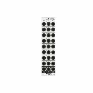
- In the upper position of the switch the upper socket of the corresponding socket triplet is connected to the centre socket
- In the lower position of the switch the lower socket of the corresponding socket triplet is connected to the centre socket
- In the centre position of the switch the sockets are not connected
Each unit of the module can be used to switch between two signals or to interrupt/connect a signal. In the last case the third socket of the triplet is not used.
The module is fully passive and both audio or control signals can be switched.
quote 731951
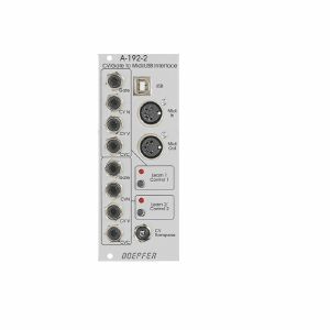
- Gate Input (min. +5V)
- CVN Input (defines the Midi note number), 1V/octave standard, range 0...+10V (i.e. 10 octaves)
- CVV Input (defines the velocity value assigned to the Midi note message), can be used alternatively for Midi volume (CC#7), range 0...+5V
- CVC Input (free assignable to any Midi control change number), range 0...+5V
For both sub-units a common CV Transpose input is available (1V/octave, range 0...+10V). The voltage applied to this input is added internally to CVN before the Midi note number is generated. It can be used e.g. to transpose two sequences simultaneously by one voltage.
How it works:
Whenever the rising edge of the Gate input is recognized a Midi note on message is generated. The note number corresponds to the sum of the voltages applied to the CVN input and the common CV Transpose Input that is present at the rising edge of the gate signal.
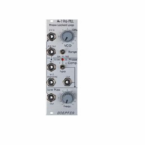
This is how a PLL works: The output of the internal VCO (linear CV control, rectangle output) is compared with an external signal (e.g. the rectangle output of a A-110 VCO) in the so-called phase comparator (PC). The output of the phase comparator is a digital signal (low/high/tristate) that indicates if the frequency resp. phase difference of the two input signals is negative, zero or positive. The output of the phase comparator is processed by a low pass filter (LPF) to generate a smooth voltage that is used to control the frequency of the internal VCO. The 3 units VCO, PC and LPF form a feedback loop that works like this: The control voltage (output of the LPF) increases as long as the external frequency is higher than the frequency of the internal VCO und stops increasing when both frequencies become identical. The control voltage decreases as long as the external frequency is lower than the frequency of the internal VCO und stops decreasing when both frequencies become identical.
But there are some stumbling blocks: Different types of phase comparators with advantages and disadvantages can be made. Some phase comparators e.g. even lock at harmonics, i.e. if the two frequencies to be compared are integer multiples. But for some applications this can be used to create interesting effects. The A-196 contains 3 different types of phase comparators: PC1 is a simple exclusive OR, that even locks at harmonics. PC2 is a so-called RS flipflop and PC3 a more complex digital memory network. The user can select one of the three phase comparators with a 3-position switch. When PC2 is used a LED displays the "locked" state, i.e. when the frequency of the internal VCO is identical to the external frequency.
Special attention has to be directed to the frequency of the LPF. To obtain a smooth control voltage for the VCO the frequency of the LPF has to be much smaller than the lowest frequency of the internal or external audio signal. Otherwise the frequency of the internal VCO will jitter or wobble around the correct frequency. But for special effects this frequency jitter can be used intentionally. Example: frequencies in the range 50Hz...1kHz have to be processed with the PLL. Therefore the frequency of the LPF has to be about 10Hz or even less. Such a low frequency of the LPF causes a noticeable slew of the internal VCO. When the frequency of the external signal jumps e.g. between 500Hz and 1kHz it takes about 0.1 second until the internal VCO reaches the new frequency (like portamento). So one has to find a compromise between frequency jitter and portamento. But these remarks are valid only for the "ideal" working PLL. As the A-196 is used in a musical environment the "problems" and disadvantages with jitter and slew time lead to additional musical applications like portamento effects, wobbling frequencies or harmonic locking according to the type of frequency comparator and time constant of the PLL low pass filter. Instead of the internal manually controlled low pass filter the voltage controlled slew limiter A-171 can be used to obtain voltage control of this parameter. Normal audio filters (e.g. A-120, A-121) cannot be used for this job as the minimum frequency is to high (down to a few Hz or even less necessary) and the signal has to be DC coupled due to the low frequencies. Audio filters are normally AC coupled.
Another very important application of a PLL is frequency multiplication in combination with an external frequency divider. For this the output of the PLL-VCO is processed through an external frequency divider (e.g. A-163, A-160, A-161, A-115) before it is fed to In1 of the phase comparator. In this case the frequency of the PLL-VCO will be a multiple of the master frequency. E.g. if the A-163 is used and adjusted to dividing factor 5 the frequency of the PLL-VCO will be 5 times the frequency of the master VCO. Consequently, frequency division (A-163) leads to frequency multiplication with the PLL circuit. In combination with the PLL low pass frequency several effects can be realized (frequency multiplication with portamento or wobbling). The frequency multiplication can even be used to drive a graphic VCO. If your graphic VCO e.g. has 8 steps (e.g. A-155) and you use a frequency divider with factor 8 in the PLL feedback the output of the graphic VCO has the same frequency as the master VCO. Another application is the generation of pseudo-harmonics (not real harmonics as only rectangle waves are available) or clock generation for switched-capacitor filters.
quote 755416
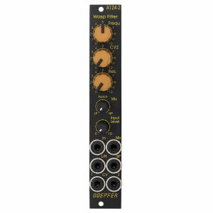
The main difference compared to the A-124 are the small controls for Mix and Input Level because for lack of space. And the lowpass or highpass signal is available at a separate socket. A jumper is used to determine if lowpass or highpass appears at the socket.
All other features are the same as the A-124.
Dimensions:
4 HP
20 mm deep
quote 1021096
inverted signal of Input 1 (labelled 1)
inverted signal of Input 2 (labelled 2)
T flipflop (toggle flipflop), controlled by Input 1, this output changes it's state whenever a the rising edge of Input 1 appears (labelled 1/2, as it works similar to a 1:2 frequency divider)
Set/Reset flipflop, this output changes it's state to "high" during the rising edge of Input 1 and turns "low" during the rising edge of Input 2 (labelled RS)
inverted output of the Set/Reset flipflop (labelled RS)
pulse output, during both the rising and falling edge of Input 1 a short trigger pulse with about 50 ms lenght is generated (labelled with the sign ± and a rectangle pulse symbol)
The outputs 2, 1/2, RS and the pulse output are equipped with LEDs that display the state of the output in question.
The output level for all six outputs can be set to 0/+5V or 0/+11V by means of a jumper on the pc board.
Voltage thresholds for the input voltages:
voltages below +0,8 V are treated as "low"
voltages above +3 V are treated as "high"
Typical applications
starting and/or stopping of events or switching operations with the RS or RS output (e.g. controlled by the trigger outputs of a sequencer, e.g. in combination with electronic switches)
generation of inverted digital signals
frequency division (1/2 output)
generation of short pulses during the rising and falling edge of a digital signal (e.g. triggering an envelope at both rising and falling edge of a gate signal).
Technical notes
The module cannot be used for bipolar signals! The negative share of the input signal will be clipped by means of a so-called clipping diode at the input of module A-165-2. This may affect the output circuitry of the module connected to the A-165-2 (depends upon the details of the output circuit and if it is protected against clipping). For the planned field of application that's normally no limitation because these signals (clock, gate, trigger) work usually only with positive voltages.
The module can be used for analog signals only to a limited extend! With analog signals the inputs of the module work as comparators and the negative share of the input signal is clipped (as mentioned above).
Width: 2HP / 10.0 mm
Depth: ? mm (measured from the rear side of the front panel)
Current: +?mA (+12V) / -?mA (-12V)
quote 1021149
Controls, In/Outputs and Functions of each VCA:
Level (manual control of the VCA amplification), small rubberized knob (L1...L4)
Control voltage input with associated attenuator (CV1...CV4), for the full VCA control range about 0...+5V control voltage are required (attenuator fully clockwise), for higher control voltages the attenuator is used, the attenuators are without knobs, just plastic shafts with white marker
Signal Input
Signal Output
All inputs and outputs are DC coupled. Consequently the VCAs can be used to process both audio and control voltages (e.g. to control the level of LFOs or envelopes)
The signal input is not equipped with an attenuator. But the VCAs can process all signals up to 15Vpp / -7.5...+7.5V without clipping. In case of higher levels an external attenuator is required (e.g. A-183-1).
The available amplification range is 0...1, the maximal amplification is 1 (i.e. it "clips" and remains at 1 even if the control voltage goes beyond the value that corresponds to amplification 1)
Functions of the voltage controlled mixers:
two outputs ("Selected" and "All")
Selected output: the ouput if a VCA is removed from this sum signal when a plug is inserted into the corresponding VCA output.
All output: sum of all VCA outputs, regardless of inserted plugs into the VCA outputs
The maximal amplification is about 0.6 to avoid clipping at the mixer outputs (otherwise the outputs may distort with 15Vpp signals at each signal input and full amplifications)
Special functions of the voltage controlled mixer (selectable by internal jumpers)
Dual Stereo VCA: In this case the control unit of VCA1 (L1 + CV1) affects also VCA3 and the control unit of VCA2 (L2 + CV2) affects also VCA4. The control units of VCA3 (L3 + CV3) and VCA4 (L4 +CV4) are out of operation.
Quad VCA: In this case the control unit of VCA1 (L1 + CV1) affects all four VCAs. The control units of VCA2, VCA3 and VCA4 are out of operation. In this mode the module has the same function as module A-132-2. That's why module A-132-2 will be discontinued.
Normalling of the signal inputs: by means of internal jumpers signal input 1 can be normalled to signal input 2, signal input 2 to signal input 3 and signal input 3 to signal input In 4. That way the same input signal can be distributed to four different channels by means of control voltages (e.g. quadrophonic distribution of audio signals). Suitable control voltage sources are e.g. A-144 (Morphing Controller) or A-143-9 (Quadrature LFO).
Additional technical specification for each VCA (based on the specifications of the VCA circuits CEM3360/AS3360 used in the module):
Crosstalk between VCAs: typ. - 80dB
Signal attenuation at 0V CV: typ. -70dB
Total harmonic distortion: typ. 1%
Control voltage feedthrough: max. 15mV
Width: 8 HP / 40.3 mm
Depth: 45 mm (measured from the rear side of the front panel)
Current: +40mA (+12V) / -40mA (-12V)
1 in stock $144.29
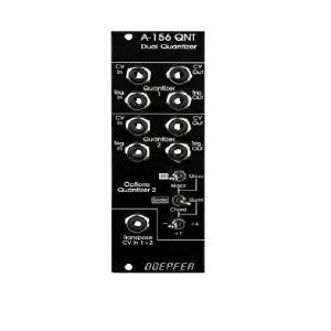
For each quantizer the following in/outputs are available:
- Control voltage input (CV In): The input for the continuous voltage to be quantized
- Control voltage output (CV Out): The output of the quantized voltage
- Trigger input (Trig.In): If this jack is left open the quantizer is working permanently. If a rectangle voltage is applied quantisation happens only at the rising edge of the signal (e.g. from an LFO or MIDI-to-Sync interface). Thus the quantizing can be synchronized with other events
- Trigger output (Trig.Out): Whenever a quantisation happens (i.e. a new voltage is generated at the CV Out) a positive pulse occurs at this output. It may be used to trigger an envelope generator (ADSR) or for triggering other modules (sequential switch A-151, trigger divider/sequencer A-160/161, trigger delay A-162, ...). If none of these functions are used the jack is left open
On top of that the A-156 is provided with a common transpose CV input having an additive effect on both quantizers. This input is quantized in semitone steps. A typical application is the transposition of a sequence generated by the A-155 by a second control voltage (e.g. coming from the MIDI-CV interface A-190).
Typical applications:
- Quantizing the CV sequence generated by an A-155 (semitone, only major scale, only minor scale and so on)
- Quantizing the voltage coming from the Trautonium Manual / Ribbon Controller A-198, Theremin A-178 or Light-to-CV module A-179 to get accurate semitones or major/minor scale tones
- Arpeggio-like effects with LFO, random, noise, envelope generators as CV sources (for negative or symmetrical voltages an offset must be added, e.g. with the offset/attenuator module A-129-3, to obtain positive voltages for the A-156 input)
Width: 8 HP / 40.3 mm
Depth: 55 mm (measured from the rear side of the front panel)
Current: +50mA (+12V) / -10mA (-12V)
1 in stock $134.14
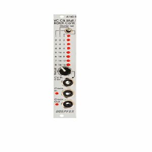
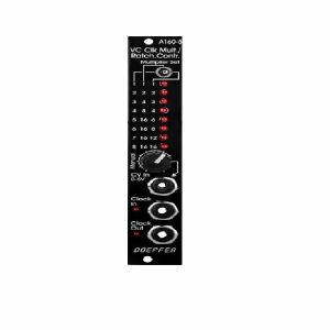
A manual control is used to adjust the clock multiplication factor manually without the need of an external control voltage. The voltage generated by this control ("Manual") is normalled to the CV In socket. As long as no plug is inserted into the CV In socket the clock multiplication factor is adjusted by means of the manual control knob and displayed by the LEDs. For dynamic applications (like the ratcheting function described below) the manually generated CV is overwritten by the external CV which has to be fed into the CV In socket.
The module can be used for all kind of clock multiplying applications. One important example is the generation of so-called ratcheting sequences. The band Tangerine Dream is famous for this kind of sequences. A normal sequencer generates only one gate signal per step. A ratcheting sequence may have also more than one gate pulses per step. This function can be obtained by using the A-160-5: one CV output of the sequencer is used to define the number of gate pulses per step. If the control of the step in question is fully CCW the generated CV is 0V and no gate signal is generated (mute of the step). When the control of the step in question is turned clockwise one, two or more gate pulses are generated depending upon the position of the mode switch and the voltage generated by the CV at this step.
Technical note: Due to the nature of clock multiplying it takes a few input clock pulses until the clock output is stable. One has to average a few input clock pulses to generate the multiplied clock output signal. Even when the input clock frequency changes it will take a few cycles until the output clock signal is correct as the module cannot foresee the future of the clock input signal. The generated clock output signal is derived from the last few cycles of the clock input signal. Consequently the module should be driven only by a clock signal with constant or slowly changing frequency.
quote 745787
A manual control is used to adjust the clock multiplication factor manually without the need of an external control voltage. The voltage generated by this control ("Manual") is normalled to the CV In socket. As long as no plug is inserted into the CV In socket the clock multiplication factor is adjusted by means of the manual control knob and displayed by the LEDs. For dynamic applications (like the ratcheting function described below) the manually generated CV is overwritten by the external CV which has to be fed into the CV In socket.
The module can be used for all kind of clock multiplying applications. One important example is the generation of so-called ratcheting sequences. The band Tangerine Dream is famous for this kind of sequences. A normal sequencer generates only one gate signal per step. A ratcheting sequence may have also more than one gate pulses per step. This function can be obtained by using the A-160-5: one CV output of the sequencer is used to define the number of gate pulses per step. If the control of the step in question is fully CCW the generated CV is 0V and no gate signal is generated (mute of the step). When the control of the step in question is turned clockwise one, two or more gate pulses are generated depending upon the position of the mode switch and the voltage generated by the CV at this step.
Technical note: Due to the nature of clock multiplying it takes a few input clock pulses until the clock output is stable. One has to average a few input clock pulses to generate the multiplied clock output signal. Even when the input clock frequency changes it will take a few cycles until the output clock signal is correct as the module cannot foresee the future of the clock input signal. The generated clock output signal is derived from the last few cycles of the clock input signal. Consequently the module should be driven only by a clock signal with constant or slowly changing frequency.
quote 745789
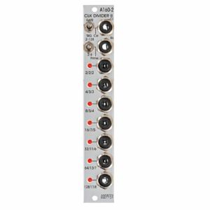
The A-160-2 also has a reset input. Whenever a reset signal is sensed, all outputs are set to certain levels which depend upon the selected mode.
These are the most important features of the module:
Three different sets of dividing factors, selected by a three-position switch at the front panel:
- Power of two: 2, 4, 8, 16, 32, 64, 128
- Prime numbers: 2, 3, 5, 7, 11, 13, 17
- Integer: 2, 3, 4, 5, 6, 7, 8
Two output modes, selected by a two-position switch at the front panel:
- Gate mode: outputs act like the outputs of typical binary dividers
- Trigger mode: in this mode the outputs are AND-wired with the clock signal (i.e. the clock pulsewidth affects the pulsewidth of the outputs)
- Clock edge type selected by a jumper on the pc board:
- Positive: the rising edge of the clock signal triggers the state change of the outputs
- Negative: the falling edge of the clock signal triggers the state change of the outputs
Reset behaviour by two jumpers on the pc board:
- Level triggered: the level at the Reset input triggers the Reset
- Edge triggered: the edge of the signal at the Reset input triggers the Reset
- Positive: a high level (> 2.5V) or the rising edge at the Reset input triggers the Reset
- Negative: a low level (< 1 V) or the falling edge at the Reset input triggers the Reset
Output polarity selected by a jumper on the pc board:
- Positive: non-inverted outputs
- Negative: all seven outputs are inverted
Width: 4HP / 20mm
Depth: 35mm (Measured from the rear side of the front panel)
Current: +12V: +50mA, -12V: -0mA
quote 671576
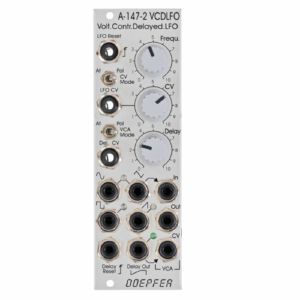
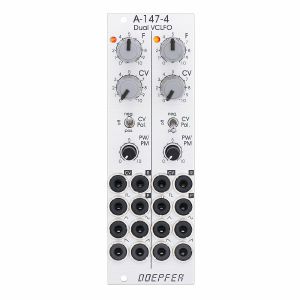
- VCLFO: voltage controlled low frequency oscillator
- VCA: voltage controlled amplifier, switchable to voltage controlled polarizer
- VC delay unit: voltage controlled linear attack envelope (only one parameter: attack) for delayed LFO operation in combination with the VCA (e.g. delayed vibrato/tremolo)
LFO: The voltage controlled LFO has the waveforms Triangle, Sine, Sawtooth and Rectangle available and features a Reset/Sync input. Triangle/Sine and Rectangle are displayed by means of dual-colour LEDs (probably red/green), Sawtooth has a unicolor LED available (probably blue). The output levels are about -4V...+4V for Triangle, Sine and Rectangle. The Sawtooth level is about 0...+8V.
The CV control can be switched to attenuator or polarizer ("CV Mode" switch). In polarizer mode the CV inputs affects the frequency in the reverse manner when the CV control is left from the centre position. In the centre position CV has no effect and right from the centre the control works like a normal attenuator. The frequency range (without external CV) is from about 0,005 Hz (i.e. about 3 minutes per period) to 200 Hz (with external CV max. frequency about 1kHz). In addition a ultra-low mode can be activated by means of an internal jumper. When the ultra-low jumper is set a fixed voltage is connected to the switching contact of the "LFO CV" socket. In polarizer mode of the CV control that way extremely low frequencies (up to one hour period and more) are possible. For this a jumper has to be installed on the pin header JP6. In the factory a dummy jumper is installed on the pin header JP7 "Dummy". JP7 has no function and is used only for "parking" of the jumper. Simply remove the jumper from JP7 and plug it on JP6. JP6 is located behind the CV control.
VCA: This is a linear VCA that can be switched to "normal" VCA (i.e. kind of a voltage controlled attenuator) or voltage controlled polarizer ("VCA Mode" switch). In the "normal" VCA mode amplification +1 is achieved with about +5V control voltage. In polarizer mode the amplification ranges from about -0.5 (i.e. inverted signal with about 50% level) with 0V CV to +0.5 (i.e. non-inverted signal with about 50% level) with +5V CV. With about +2.5V CV the signal is suppressed. Details about the functioning of a voltage controlled polarizer can be found in the description of the module A-133. In this mode the VCA can be treated also a DC coupled ring modulator (similar to A-114).
The VCA of the A-147-2 has three sockets available: "In" (signal input), "Out" (signal output) and "CV" (control voltage input).
The Triangle Output of the LFO is normalled to the VCA signal input by means of the switching contact of the "VCA In" socket. If another LFO waveform (or any other signal) should be processed by the VCA the corresponding signal has to be patched to the "VCA In" socket. The VCA can be used also independently from the LFO and the Delay CV. In this case the VCA sockets In, Out and CV have to be patched accordingly. The VCA can be used also as waveshaper for the LFO signals (e.g. by patching VCA In and VCA CV to different LFO signals, if necessary via attenuator A-183-1 or offset generator/attenuator A-183-2).
Attack/Delay: The third sub-unit of the module is a simple, voltage controlled envelope generator that has only the parameter "Delay" (or Attack) available. This unit generates a linear increasing voltage that starts from 0V after each Delay Reset until it reaches about +5V. Then the voltage remains at +5V until the next Delay Reset occurs. The inclination or gradient is controlled by the manual Delay control and the Delay control voltage ("Delay CV" input). The waveform is linear, the control scale is exponential. The output voltage is displayed by a green LED and available at the "Delay Out" socket.
The manual Delay control ranges - without external "Delay CV" - from about 5ms (fully CW) up to 2 minutes (fully CCW). By means of an external voltage applied to the "Delay CV" socket this range can be extended. A rising CV shortens the delay time (behaviour like a VCO)!
The Delay output voltage ranges from about 0V to +5V. The rising edge of the gate, clock or trigger signal applied to the "Delay Reset" sockets resets the Delay output voltage to 0 V.
"Delay Out" is normalled to the VCA CV input by means of the switching contact of the "VCA CV" socket and consequently controls the Triangle level provided that no other patch is made. A typical example is the usage of a Gate signal (e.g. from a USB/Midi-to-CV/Gate interface) as Delay Reset. That way a delayed vibrato or tremolo can be realized if the VCA output is patched to the frequency CV input of a VCO (or VCF), or the CV input of a VCA.
1 in stock $131.93
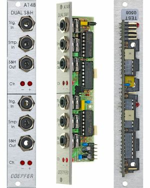
The exact shape of the staircase depends on the sort of waveform at the sample input: NOISE or RANDOM signals produce random patterns; an LFO produces rising or falling staircase patterns.
Two LEDs for each S&H indicate the voltage (positive or negative) of the sampled signal.
quote 577745
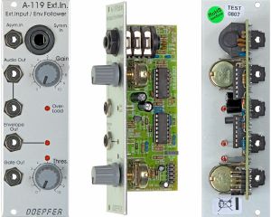
The pre-amp has two inputs: an unbalanced input for line level signals, with a gain factor of from 0 to 20, and a balanced input with a gain factor of from 0 to 500, for insertion of low level signals, for instance from a microphone or electric guitar.
The Envelope Follower reads the signal level of the input, and puts out a proportional voltage as an envelope at its own output.
The comparator generates a gate signal whenever the input goes above an adjustable trigger threshold.
Three LED's help you keep track of overload, the envelope, and the gate signal.
quote 577771
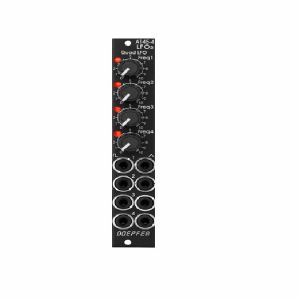
The module can be treated as a slimmed version of the quad LFO A-143-3 as it has similar features available. But the distances between the controls are smaller and rubberized small-sized knobs are used. In return the front panel has 4 HP only which is less than one third of the A-143-3. The module is primarily planned for applications where only limited space is available. The functional difference compared to the A-143-3 are the missing sawtooth outputs and frequency range switches.
quote 760210
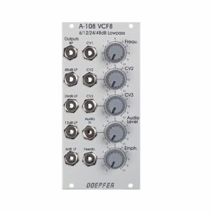
Resonance (Emphasis or Q) can be adjusted manually right up to self-oscillation, in which case the filter will behave like a sine wave oscillator. The A-108 features an external feedback input that enables the insertion of additional modules into the feedback path (e.g. VCA for voltage-controlled resonance or phaser/frequency shifter for phase/frequency shifting effects). The socket is normalized and internally connected to the 48dB low pass output if no cable is inserted into the feedback socket.
The frequency can be adjusted manually, or by voltage control. Three CV inputs (CV1, CV2, CV3) are available. CV2 and CV3 are equipped with attenuators.
The filter audio input is very sensitive so that distortion - if desired - is possible even with normal A-100 levels (e.g. VCO output). Self-oscillation will break off at high distortion levels as the internal feedback signal is drown out by the distorted audio signal. This feature may intentionally be used to create new sounds.
In combination with the Voltage Controlled Mixer A-135 and the Morphing Controller A-144 a filter with voltage-controlled slope can be realized (i.e. controlling the slope from 6dB to 48dB via CV).
1 in stock $152.30
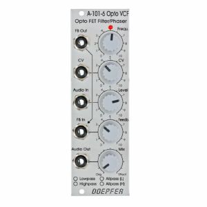
The variable resistors corresponds to the opto FET. The brightness of the Opto FET LED's, and consequently the filter frequency, can be adjusted manually (Frequ. control) and controlled by means of an external control voltage (CV) with attenuator. The LED at the front panel reflects the LED brightness inside the opto FET's.
The type of filter is chosen by jumpers on the PC board (factory setting: low pass). The type of filter determined by the jumpers positions can be marked by means of a water-resistant felt pen at the front panel.
The resonance is controlled by the Feedback control up to self-oscillation. By means of a trimming potentiometer the maximal feedback can be adjusted. High feedback values can be used mainly in the all-pass mode to obtain very extreme self-oscillation sounds. Even an external feedback signal can be used instead of the internal feedback connection (FB In socket). Whenever the filter type is changed by means of the jumpers the trimming potentiometer for the maximal feedback has to be re-adjusted.
The Mix control is used to pan between the original signal (CCW position) and the effect signal (CW position). In filter mode (LP/HP) this control is usually set fully CW. In the all-pass modes one obtains phasing sounds at centre position or "pure" all-pass sound in fully CW position.
quote 682323
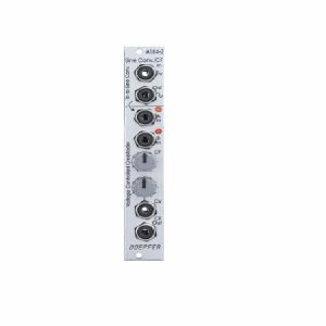
Triangle-to-Sine Waveshaper:
The upper section is a very precise triangle-to-sine converter (thanks to Tim Stinchcombe who recommended this circuit). It can be used to convert any triangle waveform into a (nearly) perfect sine. The converter is much better than the simple diode converter used in the A-110-1, A-111-1, A-145 and A-147-2. Two trimming potentiometers are used to optimize the sine shape. The converter should be assigned to one VCO or LFO because the trimming potentiometers have to be re-adjusted if the input level or DC offset of the input signal changes. If the trimming potentiometers are deliberately mis-adjusted it can be used also as a waveshaper for non-sine waveforms (e.g. sine-shaped at the top of the signal and a peak at the bottom, even voltage controlled by applying an additional voltage to the waveshaping circuit, "circuit-bending" notes will be available).
The waveform converter is DC coupled and can be used also for low frequencies (e.g. LFO triangle waves).
Voltage Controlled Crossfader:
The lower section is a voltage controlled crossfader. It has two inputs A and B. The two signals are mixed together with variable percentage. When the manual control CF is fully CCW only signal A appears at the CF Out socket. When the manual control CF is fully CW only signal B appears at the CF Out socket. In the centre position of the manual control both signal appear with the same level. In addition a control voltage input CV with attenuator is available to enable voltage control of the crossfade.
Two LEDs display the crossfading shares of input A and B.
The crossfader uses two high quality VCAs (SSM2164). Inputs and outputs are DC coupled. Consequently it can be used for audio signals and slowly varying control voltages as well.
The sockets of the upper section (triangle and sine) are normalled to the inputs A and B of the crossfader section. That way the crossfader is used to fade between triangle and sine of the VCO or LFO connected to the waveshaper. If other signals are plugged into the input sockets A and B these signals are used for crossfading.
The main application is to fade between two different waveforms of a VCO or LFO or two different VCF outputs. But the module can be used for any other signals too as the waveshaper and crossfader sections are independent apart from the normalled sockets.
2 in stock $78.91
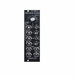
The module is equipped with four CV inputs: one with attenuator and three without attenuator. Each input is normalled to +1 V (i.e. if no plug is inserted the input contributes 1 V to the sum appearing at the output).
The input with attenuator can be used for common modulations (e.g. from an LFO, ADSR, Theremin, Pitch-Bender) for all VCOs connected to the output. The Lev.1 control is used to adjust the depth of the modulation, the first switch selects the polarity of the modulation. If no signal is connected to the first socket the attenuator works as a (fine) tuning knob because a voltage in the range 0...+1V (right position of the switch) or 0...-1V (left position of the switch) is added to the CV output.
The inputs without attenuators are planned to add control voltages coming out of keyboards, sequencers, Midi-to-CV interfaces, ribbon controllers or other CV sources that follow the 1V/oct standard. For example the CV of a keyboard can be used to transpose the CV coming from a sequencer, or the CV of a slow sequencer can be used to transpose the CV from a fast sequencer.
Each input is equipped with a three-position switch that determines if the corresponding voltage is added (right position), subtracted (left position) or if the input has no effect (centre position). If no plug is inserted the corresponding switch works as an octave switch for the lower three sections as the default 1 V are added or subtracted to the output voltage according to the switch position. The first switch can be used to add a variable voltage to the sum output. The variable voltage is adjusted with the Lev.1 control and the knob works then as kind of a (fine) tuning control.
The module is equipped with 4 outputs: three non-inverting and one inverting ouput. An internal jumper can be used to connect the non-inverted or inverted output to the CV line of the A-100 bus. That way the module can used to control several VCOs that are connected to the same bus board as the A-185-2 (same functionality as A-185-1).
1 in stock $85.20
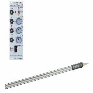
Touching the sensor with a finger generates a control voltage CV1 that is proportional to the position of the finger. The scale (i.e. the relation between position difference and voltage difference) is adjustable with a potentiometer at the front panel. A hold switch is used to determine if the CV voltage is held after removing the finger (hold = on) or if the CV voltage jumps to 0V (hold = off). In the last case (hold = off) a gate signal is derived from the CV voltage whenever a finger touches the sensor (e.g. for triggering an envelope generator).
A sensitive pressure sensor located below the position sensor generates a second control voltage CV2 that increases with higher pressure of the finger. Even for CV2 the scale is adjustable. A second gate signal is triggered as soon as the pressure exceeds a certain value. The gate threshold is adjustable at the front panel.
The sensors are located in a separate metal frame (length about 600 mm, width about 30 mm, height about 18 mm, weight: about 900 g, colour: silver-grey). The connection between the module and the sensor frame is made by a 4 pin cable (same as used for USB connections).
Typical applications:
- Trautonium manual, the string is replaced by the position sensor that is much easier to use and cheaper than the string. In combination with the Subharmonic Oscillator A-113, the Trautonium Filter A-104 and some auxiliary modules a complete Trautonium replica may be realized. In combination with the Quantizer A-156 exact semitone intervals are possible.
- Ribbon Controller for any A-100 parameter
1 in stock $223.00
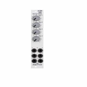
The module is the slim version of module A-138a and offers nearly the same features. But the distances between the controls are smaller and rubberized small-sized knobs are used. In return the front panel has 4 HP only which is half the width of the A-138a. The module is primarily planned for applications where only limited space is available. The only functional difference compared to the A-138a is the missing attenuator for the (dual) output.
Width: 4HP / 20.0 mm
Depth: 30 mm (measured from the rear side of the front panel)
Current: +10mA (+12V) / -10mA (-12V)
2 in stock $58.04
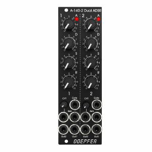
Each ADSR provides these controls and in/outputs:
- LED (displays the envelope output)
- A: manual Attack control
- D: manual Decay control
- S: manual Sustain control
- R: manual Release control
- Gate Input
- Retrigger Input
- CVT Input with attenuator (CVT = CV Time)
- Envelope Output 1
- Envelope Output 2
The output voltage range for each envelope is 0 - 10V (10V = attack peak).
The time range of Attack/Decay/Release is about 1ms to 30s.
By means of internal jumpers one can select which time parameters are controlled by the CVT input (e.g. D only or D+R or A+D+R) and in which direction (i.e. if an increasing CVT shortens or stretches the time parameter in question).
Socket CVT can be normalled to an internal fixed voltage (i.e. the switching contact is connected to an internal fixed voltage). That way it's possible to change all time parameters simultaneously by means of the CVT control.
Another jumper is used to set output 2 to normal or inverted envelope.
And another jumper is used for the normalling of Gate 2 to Gate 1 (i.e. ADSR#2 is also triggered by Gate 1).
Two more jumpers are used for the optional bus access to the gate signal of the bus for each ADSR.
1 in stock $160.47
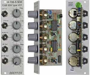
The filter is equipped with a band pass output and a combined low/notch/high pass output. For this output a control knob defines the relation between low and high pass signal. If both signals appear at the same level (i.e. middle position of the Mix knob) one obtains a notch filter. Otherwise the low or high pass signal predominates.
The module does not feature self-oscillation in contrast to most of the other filters of the A-100 system.
The module generates a distorted audio signal if the level control is set to about 50% (i.e. centre position) or more with A-100 standard signals like VCOs.
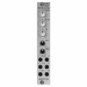
It is the successor of the A-105 which had to be discontinued because the obsolete SSM2044 filter circuit. The A-105-2 is based on the SSI2144 which is in turn the successor circuit of the SSM2044. The features of both modules are nearly the same. The main difference is the clearly reduced front panel width of the A-105-2 (4HP instead of 8HP) and the associated changes of the controls and sockets positions. In addition the A-105-2 is equipped with 2 audio inputs.
The module has these controls and in/outputs available:
Control Frequ: manual frequency control
Control FCV2: attenuator for the frequency control voltage applied to socket FCV2
Control Q: manual resonance control
Control QCV: attenuator for the resonance control voltage applied to socket QCV
Control Input 1 Level: attenuator for the audio input signal applied to socket Input 1
Socket Input 1: audio input 1 (with attenuator)
Socket Input 2: audio input 2 (without attenuator)
Socket FCV1: frequency control voltage 1 (without attenuator, about 1V/oct scale)
Socket FCV2: frequency control voltage 2 (with attenuator)
Socket QCV: resonance control voltage (with attenuator)
Socket Out: audio output
Technical notes:
Frequency range: about 15Hz ... 15 kHz
Resonance up to self oscillation
Max. input voltage at Input 2 without clipping/distortion: about 15Vpp
Max. output voltage without clipping/distortion: about 15Vpp
The signals of both inputs are mixed before they are processed by the filter. This saves an external mixer for small setups.
Depth: 45 mm
HP : 4