
 USD
USD


Receive new release alerts for Doepfer
Filter

Equipment
Format
Featured
Price
Items 1 to 10 of 10 on page 1 of 1
People also bought...
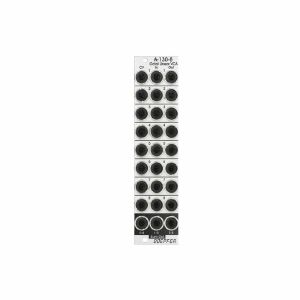
Doepfer A-130-8 Octal Linear VCA Module (slim line series, silver) (VCA synth module)
Cat: 765896 Rel: 28 Jul 20
Octal linear voltage controlled amplifier module - 6HP
Notes: Module A-130-8 contains eight linear voltage controlled amplifiers (VCAs). Each VCA features a control voltage input (CV), a signal input (In) and a signal output (Out). In addition three mixers are included: the socket labelled "1-4" outputs the sum of the VCAs 1-4, the socket labelled "5-8" outputs the sum of the VCAs 5-8, the socket labelled "1-8" outputs the sum of all eight VCAs.
The signal inputs are able to process levels up to about 20Vpp without clipping (20Vpp = 20V peak-to-peak or about -10V...+10V) . Each CV input is equipped with a trimming potentiometer that is used to adjust the sensitivity of the CV input in question. In the factory the module is adjusted for the CV range 0...+5V but can be re-adjusted by the user for other control voltage ranges (e.g. 0...+10V).
The amplification range for each single VCA is 0...1. The signals of the sum outputs have a lower amplification to avoid distortion at the sum outputs.
The VCAs and mixers are fully DC coupled, i.e. the module can be used for the processing of both audio and control voltage signals. The control voltage and signal inputs can be normalled by means of small solder pads (e.g. 1 > 2 > 3 > 4 and so on, or 1 > 5, 2 > 6, 3 > 7, 4 > 8 for the stereo application mentioned below).
Typical applications
any kind of VCA application (e.g. voltage controlled attenuation of audio or control voltage signals)
two voltage controlled mixers with four channels each
voltage controlled stereo mixer with four channels each, for this the control voltage inputs have to be correspondingly patched or internally normalled: CV1=CV5 /CV 2=CV6 / CV3=CV7 / CV4=CV8
voltage controlled mixer with eight channels
add-on for the Joystick module A-174-4
Technical notes
The following document shows the positions and functions of the jumpers and trimming potentiometers of the module: A130_8_trimming_potentiometers_and_jumpers.pdf
When the trimming potentiometer in question is moved CCW (counterclockwise) the sensitivity of the CV input in question increases (view to the top edge of the module).
Trimming procedure: apply the max. CV voltage that will occur in your application (e.g. +8V) to the CV input and a constant audio signal to the audio input (e.g. a VCO sawtooth). Then adjust the trimming potentiometer in question until the max. output level is reached and does not become higher even if the trimming potentiometer is turned further. Possible the the trimming potentiometer has to be turned back again a bit to find the correct position.
With the trimming potentiometer adjusted to max. sensitivity the linear amplification starts at about +0.1 control voltage (CV). We introduced this small dead range of about 100 mV to make sure that the VCA fully closes with CV = 0V.
It's possible to change the amplifications of the internal mixers used for the sum outputs (1-4, 1-8, 5-8) also to 1. Pay attention that then clipping/distortion may occur at the sum outputs. For this the 22k resistors R41 (Sum 1-4), R44 (Sum 5-8) und R51 (Sum 1-8) have to be replaced by 47k. As they are smd resistors sufficient experience with soldering/desoldering of smd parts is essential. And we have to point out that warranty is void if such modifications are carried out by the customer. The positions of the resistors are shown in the document A130_8_trimming_potentiometers_and_jumpers.pdf.
If multiple exponential VCAs are required module A-132-4 is recommended.
Width: 6 HP / 30.1 mm
Depth: 40 mm (measured from the rear side of the front panel)
Current: +50 mA (+12V) / -50 mA (-12V)
… Read moreThe signal inputs are able to process levels up to about 20Vpp without clipping (20Vpp = 20V peak-to-peak or about -10V...+10V) . Each CV input is equipped with a trimming potentiometer that is used to adjust the sensitivity of the CV input in question. In the factory the module is adjusted for the CV range 0...+5V but can be re-adjusted by the user for other control voltage ranges (e.g. 0...+10V).
The amplification range for each single VCA is 0...1. The signals of the sum outputs have a lower amplification to avoid distortion at the sum outputs.
The VCAs and mixers are fully DC coupled, i.e. the module can be used for the processing of both audio and control voltage signals. The control voltage and signal inputs can be normalled by means of small solder pads (e.g. 1 > 2 > 3 > 4 and so on, or 1 > 5, 2 > 6, 3 > 7, 4 > 8 for the stereo application mentioned below).
Typical applications
any kind of VCA application (e.g. voltage controlled attenuation of audio or control voltage signals)
two voltage controlled mixers with four channels each
voltage controlled stereo mixer with four channels each, for this the control voltage inputs have to be correspondingly patched or internally normalled: CV1=CV5 /CV 2=CV6 / CV3=CV7 / CV4=CV8
voltage controlled mixer with eight channels
add-on for the Joystick module A-174-4
Technical notes
The following document shows the positions and functions of the jumpers and trimming potentiometers of the module: A130_8_trimming_potentiometers_and_jumpers.pdf
When the trimming potentiometer in question is moved CCW (counterclockwise) the sensitivity of the CV input in question increases (view to the top edge of the module).
Trimming procedure: apply the max. CV voltage that will occur in your application (e.g. +8V) to the CV input and a constant audio signal to the audio input (e.g. a VCO sawtooth). Then adjust the trimming potentiometer in question until the max. output level is reached and does not become higher even if the trimming potentiometer is turned further. Possible the the trimming potentiometer has to be turned back again a bit to find the correct position.
With the trimming potentiometer adjusted to max. sensitivity the linear amplification starts at about +0.1 control voltage (CV). We introduced this small dead range of about 100 mV to make sure that the VCA fully closes with CV = 0V.
It's possible to change the amplifications of the internal mixers used for the sum outputs (1-4, 1-8, 5-8) also to 1. Pay attention that then clipping/distortion may occur at the sum outputs. For this the 22k resistors R41 (Sum 1-4), R44 (Sum 5-8) und R51 (Sum 1-8) have to be replaced by 47k. As they are smd resistors sufficient experience with soldering/desoldering of smd parts is essential. And we have to point out that warranty is void if such modifications are carried out by the customer. The positions of the resistors are shown in the document A130_8_trimming_potentiometers_and_jumpers.pdf.
If multiple exponential VCAs are required module A-132-4 is recommended.
Width: 6 HP / 30.1 mm
Depth: 40 mm (measured from the rear side of the front panel)
Current: +50 mA (+12V) / -50 mA (-12V)
1 in stock $112.32
People also bought...
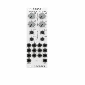
Doepfer A-135-2 Quad VCA & Voltage Controller Mixer Module (silver) (VCA/mixer synth module)
Cat: 714704 Rel: 22 Jan 19
Compact voltage-controlled four-channel audio mixer - 8HP
Notes: A-135-2 is a miniature version of the A-135-1. Behind a front panel with 8 HP only four linear VCAs (voltage controlled amplifiers) and a voltage controlled mixer based on the VCAs are available.
Controls, In/Outputs and Functions of each VCA:
- Level (manual control of the VCA amplification), small rubberized knob (L1...L4)
- Control voltage input with associated attenuator (CV1...CV4), for the full VCA control range about 0...+5V control voltage are required (attenuator fully clockwise), for higher control voltages the attenuator is used, the attenuators are without knobs, just plastic shafts with white marker
- Signal Input
- Signal Output
- All inputs and outputs are DC coupled. Consequently the VCAs can be used to process both audio and control voltages (e.g. to control the level of LFOs or envelopes)
- The signal input is not equipped with an attenuator. But the VCAs can process all signals up to 15Vpp / -7.5...+7.5V without clipping. In case of higher levels an external attenuator is required (e.g. A-183-1).
- The available amplification range is 0...1, the maximal amplification is 1 (i.e. it "clips" and remains at 1 even if the control voltage goes beyond the value that corresponds to amplification 1)
Functions of the voltage controlled mixers:
- Two outputs ("Selected" and "All")
- Selected output: the ouput if a VCA is removed from this sum signal when a plug is inserted into the corresponding VCA output.
- All output: sum of all VCA outputs, regardless of inserted plugs into the VCA outputs
- The maximal amplification is about 0.6 to avoid clipping at the mixer outputs (otherwise the outputs may distort with 15Vpp signals at each signal input and full amplifications)
Special functions of the voltage controlled mixers (selectable by internal jumpers):
- Dual Stereo VCA: In this case the control unit of VCA1 (L1 + CV1) affects also VCA3 and the control unit of VCA2 (L2 + CV2) affects also VCA4, the control units of VCA2 and VCA4 are out of operation
- Quad VCA: In this case the control unit of VCA1 (L1 + CV1) affects all four VCAs. The control units of VCA2, VCA3 and VCA4 are out of operation. In this mode the module has the same function as module A-132-2. That's why module A-132-2 will be discontinued.
- Normalling of the signal inputs: by means of internal jumpers signal input 1 can be normalled to signal input 2, signal input 2 to signal input 3 and signal input 3 to signal input In 4. That way the same input signal can be distributed to four different channels by means of control voltages (e.g. quadrophonic distribution of audio signals). Suitable control voltage sources are e.g. A-144 (Morphing Controller) or A-143-9 (Quadrature LFO).
… Read moreControls, In/Outputs and Functions of each VCA:
- Level (manual control of the VCA amplification), small rubberized knob (L1...L4)
- Control voltage input with associated attenuator (CV1...CV4), for the full VCA control range about 0...+5V control voltage are required (attenuator fully clockwise), for higher control voltages the attenuator is used, the attenuators are without knobs, just plastic shafts with white marker
- Signal Input
- Signal Output
- All inputs and outputs are DC coupled. Consequently the VCAs can be used to process both audio and control voltages (e.g. to control the level of LFOs or envelopes)
- The signal input is not equipped with an attenuator. But the VCAs can process all signals up to 15Vpp / -7.5...+7.5V without clipping. In case of higher levels an external attenuator is required (e.g. A-183-1).
- The available amplification range is 0...1, the maximal amplification is 1 (i.e. it "clips" and remains at 1 even if the control voltage goes beyond the value that corresponds to amplification 1)
Functions of the voltage controlled mixers:
- Two outputs ("Selected" and "All")
- Selected output: the ouput if a VCA is removed from this sum signal when a plug is inserted into the corresponding VCA output.
- All output: sum of all VCA outputs, regardless of inserted plugs into the VCA outputs
- The maximal amplification is about 0.6 to avoid clipping at the mixer outputs (otherwise the outputs may distort with 15Vpp signals at each signal input and full amplifications)
Special functions of the voltage controlled mixers (selectable by internal jumpers):
- Dual Stereo VCA: In this case the control unit of VCA1 (L1 + CV1) affects also VCA3 and the control unit of VCA2 (L2 + CV2) affects also VCA4, the control units of VCA2 and VCA4 are out of operation
- Quad VCA: In this case the control unit of VCA1 (L1 + CV1) affects all four VCAs. The control units of VCA2, VCA3 and VCA4 are out of operation. In this mode the module has the same function as module A-132-2. That's why module A-132-2 will be discontinued.
- Normalling of the signal inputs: by means of internal jumpers signal input 1 can be normalled to signal input 2, signal input 2 to signal input 3 and signal input 3 to signal input In 4. That way the same input signal can be distributed to four different channels by means of control voltages (e.g. quadrophonic distribution of audio signals). Suitable control voltage sources are e.g. A-144 (Morphing Controller) or A-143-9 (Quadrature LFO).
1 in stock $131.76
People also bought...
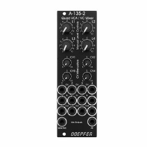
Doepfer A-135-2v Quad VCA & VC Mixer Vintage Edition Module (black) (modular synthesiser)
Cat: 790453 Rel: 30 Oct 20
Quad voltage controlled amplifier & mixer module - 8HP
Notes: A-135-2 is a miniature version of the A-135-1. Behind a front panel with 8 HP only four linear VCAs (voltage controlled amplifiers) and a voltage controlled mixer based on the VCAs are available.
Controls, In/Outputs and Functions of each VCA:
Level (manual control of the VCA amplification), small rubberized knob (L1...L4)
Control voltage input with associated attenuator (CV1...CV4), for the full VCA control range about 0...+5V control voltage are required (attenuator fully clockwise), for higher control voltages the attenuator is used, the attenuators are without knobs, just plastic shafts with white marker
Signal Input
Signal Output
All inputs and outputs are DC coupled. Consequently the VCAs can be used to process both audio and control voltages (e.g. to control the level of LFOs or envelopes)
The signal input is not equipped with an attenuator. But the VCAs can process all signals up to 15Vpp / -7.5...+7.5V without clipping. In case of higher levels an external attenuator is required (e.g. A-183-1).
The available amplification range is 0...1, the maximal amplification is 1 (i.e. it "clips" and remains at 1 even if the control voltage goes beyond the value that corresponds to amplification 1)
Functions of the voltage controlled mixers:
two outputs ("Selected" and "All")
Selected output: the ouput if a VCA is removed from this sum signal when a plug is inserted into the corresponding VCA output.
All output: sum of all VCA outputs, regardless of inserted plugs into the VCA outputs
The maximal amplification is about 0.6 to avoid clipping at the mixer outputs (otherwise the outputs may distort with 15Vpp signals at each signal input and full amplifications)
Special functions of the voltage controlled mixer (selectable by internal jumpers)
Dual Stereo VCA: In this case the control unit of VCA1 (L1 + CV1) affects also VCA3 and the control unit of VCA2 (L2 + CV2) affects also VCA4. The control units of VCA3 (L3 + CV3) and VCA4 (L4 +CV4) are out of operation.
Quad VCA: In this case the control unit of VCA1 (L1 + CV1) affects all four VCAs. The control units of VCA2, VCA3 and VCA4 are out of operation. In this mode the module has the same function as module A-132-2. That's why module A-132-2 will be discontinued.
Normalling of the signal inputs: by means of internal jumpers signal input 1 can be normalled to signal input 2, signal input 2 to signal input 3 and signal input 3 to signal input In 4. That way the same input signal can be distributed to four different channels by means of control voltages (e.g. quadrophonic distribution of audio signals). Suitable control voltage sources are e.g. A-144 (Morphing Controller) or A-143-9 (Quadrature LFO).
Additional technical specification for each VCA (based on the specifications of the VCA circuits CEM3360/AS3360 used in the module):
Crosstalk between VCAs: typ. - 80dB
Signal attenuation at 0V CV: typ. -70dB
Total harmonic distortion: typ. 1%
Control voltage feedthrough: max. 15mV
Width: 8 HP / 40.3 mm
Depth: 45 mm (measured from the rear side of the front panel)
Current: +40mA (+12V) / -40mA (-12V)
… Read moreControls, In/Outputs and Functions of each VCA:
Level (manual control of the VCA amplification), small rubberized knob (L1...L4)
Control voltage input with associated attenuator (CV1...CV4), for the full VCA control range about 0...+5V control voltage are required (attenuator fully clockwise), for higher control voltages the attenuator is used, the attenuators are without knobs, just plastic shafts with white marker
Signal Input
Signal Output
All inputs and outputs are DC coupled. Consequently the VCAs can be used to process both audio and control voltages (e.g. to control the level of LFOs or envelopes)
The signal input is not equipped with an attenuator. But the VCAs can process all signals up to 15Vpp / -7.5...+7.5V without clipping. In case of higher levels an external attenuator is required (e.g. A-183-1).
The available amplification range is 0...1, the maximal amplification is 1 (i.e. it "clips" and remains at 1 even if the control voltage goes beyond the value that corresponds to amplification 1)
Functions of the voltage controlled mixers:
two outputs ("Selected" and "All")
Selected output: the ouput if a VCA is removed from this sum signal when a plug is inserted into the corresponding VCA output.
All output: sum of all VCA outputs, regardless of inserted plugs into the VCA outputs
The maximal amplification is about 0.6 to avoid clipping at the mixer outputs (otherwise the outputs may distort with 15Vpp signals at each signal input and full amplifications)
Special functions of the voltage controlled mixer (selectable by internal jumpers)
Dual Stereo VCA: In this case the control unit of VCA1 (L1 + CV1) affects also VCA3 and the control unit of VCA2 (L2 + CV2) affects also VCA4. The control units of VCA3 (L3 + CV3) and VCA4 (L4 +CV4) are out of operation.
Quad VCA: In this case the control unit of VCA1 (L1 + CV1) affects all four VCAs. The control units of VCA2, VCA3 and VCA4 are out of operation. In this mode the module has the same function as module A-132-2. That's why module A-132-2 will be discontinued.
Normalling of the signal inputs: by means of internal jumpers signal input 1 can be normalled to signal input 2, signal input 2 to signal input 3 and signal input 3 to signal input In 4. That way the same input signal can be distributed to four different channels by means of control voltages (e.g. quadrophonic distribution of audio signals). Suitable control voltage sources are e.g. A-144 (Morphing Controller) or A-143-9 (Quadrature LFO).
Additional technical specification for each VCA (based on the specifications of the VCA circuits CEM3360/AS3360 used in the module):
Crosstalk between VCAs: typ. - 80dB
Signal attenuation at 0V CV: typ. -70dB
Total harmonic distortion: typ. 1%
Control voltage feedthrough: max. 15mV
Width: 8 HP / 40.3 mm
Depth: 45 mm (measured from the rear side of the front panel)
Current: +40mA (+12V) / -40mA (-12V)
1 in stock $141.73
People also bought...
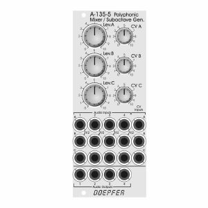
Doepfer A-135-5 Polyphonic Mixer/Suboctave Generator Module (silver) (mixer synth module)
Cat: 945421 Rel: 19 Oct 23
Polyphonic voltage controlled mixer & suboctave generator module - 10HP.
Notes: Module A-135-5 is a combination of a voltage controlled polyphonic mixer and a polyphonic suboctave generator. It is made of 12 voltage controlled amplifiers (VCAs) which are arranged in form of a 4x3 matrix. Herewith up to three four-voice polyphonic signals (e.g. the outputs of three polyphonic VCOs A-111-4) can be mixed. The level of each of the three polyphonic channels (A, B, C) with four voices each can be controlled manually or by means of an external control voltage with associated attenuators.
In addition the module features four frequency dividers which derive the suboctaves from the four input signals of channel A. The suboctave signals are wired to the switching contacts of the sockets of channel B. As long as the sockets of channel B are not patched the suboctave signals of channel A are used as inputs for channel B. The suboctaves are symmetrical rectangle waves with half the frequency of the corresponding signal A. For example two polyphonic VCOs A-111-4) can be used and patched to the channels A and C. Channel B then provides the suboctaves of channel A.
As the module is fully DC coupled it can be used also for the mixing of control voltages in a polyphonic environment (e.g. for envelopes, LFOs or other control voltages).
The switching contacts of the 12 input sockets and the four outputs are internally connected to pin headers. That way the module can be internally pre-patched to other polyphonic modules (e.g. the four inputs A to an A-111-4, the four inputs C to another A-111-4 and the outputs to the polyphonic filter A-105-4). As the switching contacts of the sockets are used for the internal pre-patching the internal patch can be overridden by using the sockets at the front panel.
The module has these controls and in/outputs available:
Controls Lev.A, Lev.B, Lev.C: manual level adjustment of the channels A, B and C
Controls CV A, CV B, CV C: attenuators for the corresponding control voltage inputs
Sockets A1...4: inputs channel A
Sockets B1...4: inputs channel B (if the sockets are not patched the suboctave signals are used for the inputs B)
Sockets C1...4: inputs channel C
Sockets CV A. CV B, CV C: control voltage inputs for the channels A, B and C
Sockets Out 1...4: outputs
Dimensions
10 HP
55 mm deep
… Read moreIn addition the module features four frequency dividers which derive the suboctaves from the four input signals of channel A. The suboctave signals are wired to the switching contacts of the sockets of channel B. As long as the sockets of channel B are not patched the suboctave signals of channel A are used as inputs for channel B. The suboctaves are symmetrical rectangle waves with half the frequency of the corresponding signal A. For example two polyphonic VCOs A-111-4) can be used and patched to the channels A and C. Channel B then provides the suboctaves of channel A.
As the module is fully DC coupled it can be used also for the mixing of control voltages in a polyphonic environment (e.g. for envelopes, LFOs or other control voltages).
The switching contacts of the 12 input sockets and the four outputs are internally connected to pin headers. That way the module can be internally pre-patched to other polyphonic modules (e.g. the four inputs A to an A-111-4, the four inputs C to another A-111-4 and the outputs to the polyphonic filter A-105-4). As the switching contacts of the sockets are used for the internal pre-patching the internal patch can be overridden by using the sockets at the front panel.
The module has these controls and in/outputs available:
Controls Lev.A, Lev.B, Lev.C: manual level adjustment of the channels A, B and C
Controls CV A, CV B, CV C: attenuators for the corresponding control voltage inputs
Sockets A1...4: inputs channel A
Sockets B1...4: inputs channel B (if the sockets are not patched the suboctave signals are used for the inputs B)
Sockets C1...4: inputs channel C
Sockets CV A. CV B, CV C: control voltage inputs for the channels A, B and C
Sockets Out 1...4: outputs
Dimensions
10 HP
55 mm deep
1 in stock $170.52
Click for better price!
or call +44 20 7424 1960
quote 945421
quote 945421
People also bought...
Doepfer A-138b 4-Channel Mixer Logarithmic Module (silver) (mixer synth module)
Cat: 577776 Rel: 29 Nov 17
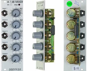
Four channel mixer module - 8HP
Notes: Module A-138 is a four channel mixer, which can be used with either control voltages or audio signals. Each of the four inputs has an attenuator, and there's a master attenuator, so that the mixer can be used at the end of the audio chain, i.e. it can be used to interface directly with an external mixer, amplifier, etc.
The A-138b has potentiometers with logarithmic response, so is especially suitable for audio signal mixing.
… Read moreThe A-138b has potentiometers with logarithmic response, so is especially suitable for audio signal mixing.
1 in stock $65.32
Click for better price!
or call +44 20 7424 1960
quote 577776
quote 577776
People also bought...
Doepfer A-138m 4x4 Matrix Mixer Module (mixer synth module)
Cat: 716959 Rel: 29 Jan 19
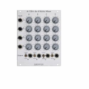
4x4 matrix mixer module - 20HP
Notes: Module A-138m is a 4 x 4 matrix mixer with switches for unipolar/bipolar mode for each column. Unipolar means that the controls work as attenuators. Bipolar means that the controls work as polarizers. In this mode the amplification is zero in the middle position of the corresponding control. Turning the knob counterclockwise from the center position the signal is subtracted from the output sum with increasing amount (i.e. negative). Turning the knob clockwise from the center position the signal is added to the output sum with increasing amount. The module is DC-coupled and can be used for both audio and control voltage mixing.
By means of an internal jumper one can select if the four upper controls work as DC offset generators - provided that no patch cord is plugged into the upper input socket. If this feature is not required it can be deactivated by removing the jumper on top left of the pc board. The function is identical to the A-138a/b.
Dimensions
20 HP
20 mm deep
Current Draw
30 mA +12V
30 mA -12V
… Read moreBy means of an internal jumper one can select if the four upper controls work as DC offset generators - provided that no patch cord is plugged into the upper input socket. If this feature is not required it can be deactivated by removing the jumper on top left of the pc board. The function is identical to the A-138a/b.
Dimensions
20 HP
20 mm deep
Current Draw
30 mA +12V
30 mA -12V
1 in stock $151.70
People also bought...
Doepfer A-138n Narrow Mixer Module (silver, slim line series) (mixer synth module)
Cat: 731947 Rel: 10 Jun 19
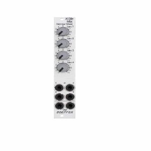
4-channel mixer module - 4HP
Notes: Module A-138n is a simple four channel mixer, which can be used with either control voltages or audio signals. Each of the four inputs has an attenuator available. The output is twice available (two sockets, hard-wired like a multiple).
The module is the slim version of module A-138a and offers nearly the same features. But the distances between the controls are smaller and rubberized small-sized knobs are used. In return the front panel has 4 HP only which is half the width of the A-138a. The module is primarily planned for applications where only limited space is available. The only functional difference compared to the A-138a is the missing attenuator for the (dual) output.
Width: 4HP / 20.0 mm
Depth: 30 mm (measured from the rear side of the front panel)
Current: +10mA (+12V) / -10mA (-12V)
… Read moreThe module is the slim version of module A-138a and offers nearly the same features. But the distances between the controls are smaller and rubberized small-sized knobs are used. In return the front panel has 4 HP only which is half the width of the A-138a. The module is primarily planned for applications where only limited space is available. The only functional difference compared to the A-138a is the missing attenuator for the (dual) output.
Width: 4HP / 20.0 mm
Depth: 30 mm (measured from the rear side of the front panel)
Current: +10mA (+12V) / -10mA (-12V)
2 in stock $61.46
People also bought...
Doepfer A-138nv Narrow Mini Mixer Vintage Edition Module (black) (mixer/quad synth module)
Cat: 760211 Rel: 06 Mar 20
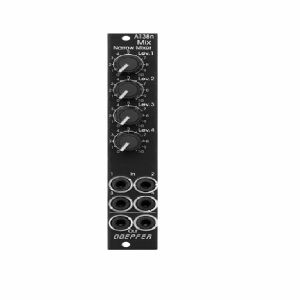
Narrow mini mixer module - 4HP.
Notes: Compact and simple four-input mixer module from Uncle Dieter. Linear pots make it suited to mixing CV signals but it can also handle audio. Mixed signal hard-wired to two sockets.
Supplier notes:
Module A-138n is a simple four channel mixer, which can be used with either control voltages or audio signals. Each of the four inputs has an attenuator available. The output is twice available (two sockets, hard-wired like a multiple).
HP : 4
… Read moreSupplier notes:
Module A-138n is a simple four channel mixer, which can be used with either control voltages or audio signals. Each of the four inputs has an attenuator available. The output is twice available (two sockets, hard-wired like a multiple).
HP : 4
1 in stock $74.19
Click for better price!
or call +44 20 7424 1960
quote 760211
quote 760211
People also bought...
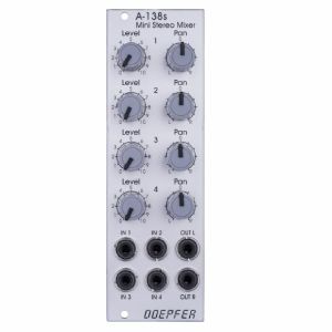
Doepfer A-138s Mini Stereo Mixer Module (silver) (mixer synth module)
Cat: 671589 Rel: 29 Nov 17
Four-channel stereo mixer - 8HP
Notes: A-138s is a simple but useful 4-in-2 mixing tool. It has four inputs available. Each input is equipped with an attenuator (Level) and a panning control that is used to distribute the signal to the left and right output. Beyond stereo mixing it is equally suited to create variable parallel routings. For example: Any of the four inputs may be routed in variable intensity to feed two filters.
You may regard the A-138s as a smaller version of the A-138m Matrix Mixer.
Inputs and outputs are DC coupled, i.e. the module can be used for the mixing of control signals too.
- 3U Eurorack module, 8 HP wide, 30 mm in depth
- Power consumption: 10 mA at +12 V and 10 mA at -12 V
… Read moreYou may regard the A-138s as a smaller version of the A-138m Matrix Mixer.
Inputs and outputs are DC coupled, i.e. the module can be used for the mixing of control signals too.
- 3U Eurorack module, 8 HP wide, 30 mm in depth
- Power consumption: 10 mA at +12 V and 10 mA at -12 V
1 in stock $85.26
Click for better price!
or call +44 20 7424 1960
quote 671589
quote 671589
People also bought...
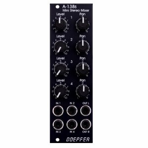
Doepfer A-138sv Mini Stereo Mixer Vintage Edition Module (black) (mixer synth module)
Cat: 684443 Rel: 30 Apr 18
Four-channel stereo mixer - 8HP
Notes: A-138s is a simple but useful 4-in-2 mixing tool. It has four inputs available. Each input is equipped with an attenuator (Level) and a panning control that is used to distribute the signal to the left and right output. Beyond stereo mixing it is equally suited to create variable parallel routings. For example: Any of the four inputs may be routed in variable intensity to feed two filters.
You may regard the A-138s as a smaller version of the A-138m Matrix Mixer.
Inputs and outputs are DC coupled, i.e. the module can be used for the mixing of control signals too.
- 3U Eurorack module, 8 HP wide, 30 mm in depth
- Power consumption: 10 mA at +12 V and 10 mA at -12 V
… Read moreYou may regard the A-138s as a smaller version of the A-138m Matrix Mixer.
Inputs and outputs are DC coupled, i.e. the module can be used for the mixing of control signals too.
- 3U Eurorack module, 8 HP wide, 30 mm in depth
- Power consumption: 10 mA at +12 V and 10 mA at -12 V
2 in stock $88.58
Items 1 to 10 of 10 on page 1 of 1
