100% Secure Shopping
Studio equipment
Our full range of studio equipment from all the leading equipment and software brands. Guaranteed fast delivery and low prices.
100% Secure Shopping
DJ equipment
Our full range of DJ equipment from all the leading equipment and software brands. Guaranteed fast delivery and low prices. Visit Juno DJ


Filter
Stock
Coming Soon
Equipment
Format
Brand
Featured
Price
Tags
People also bought...
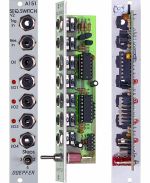
Doepfer A-151 Quad Sequential Switch Module (silver) (switch/quad synth module)
Cat: 577792 Rel: 06 Jun 19
Electronic switch with up to four steps - 4HP
Notes: Module A-151 (Quad Sequential Switch) is like an electronic four-position rotary switch.
It includes trigger and reset inputs, four in / outputs, and a common out / input. Each time a pulse is received at the trigger input socket, the common out / input is connected to the next in / output. After the fourth in / output, the next trigger makes it step back to the first again, and so on. A positive pulse at the reset input switches the out / input immediately back to the first in / output (see Fig. 1). Voltages in the range -8V...+8V at the O/I resp. I/O sockets can be processed by the module.
Four LEDs indicate the active in / output (i.e. the on that is connected to the out / input at any particular time).
… Read moreIt includes trigger and reset inputs, four in / outputs, and a common out / input. Each time a pulse is received at the trigger input socket, the common out / input is connected to the next in / output. After the fourth in / output, the next trigger makes it step back to the first again, and so on. A positive pulse at the reset input switches the out / input immediately back to the first in / output (see Fig. 1). Voltages in the range -8V...+8V at the O/I resp. I/O sockets can be processed by the module.
Four LEDs indicate the active in / output (i.e. the on that is connected to the out / input at any particular time).
4 in stock $58.08
Click for better price!
or call +44 20 7424 1960
quote 577792
quote 577792
People also bought...
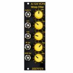
Doepfer A-124 VCF5 Wasp Filter 12dB Multimode Filter Module (special edition, black/yellow) (filter synth module)
Cat: 671564 Rel: 29 Nov 17
12dB multi-mode filter with unique classic circuitry, based on the filter from the 70s EDP Wasp synth
Notes: Module A-124 is a special 12dB multimode filter using the "strange" filter circuit of the "EDP Wasp" (an analog synthesizer with black/yellow case built end of the seventies, manufactured by the UK company "Electronic Dream Plant" with Chris Huggett und Adrian Wagner). This design "abuses" digital inverters as analog operational amplifiers leading to distortions and other "dirty" effects that generate the specific sound of this filter. The filter is equipped with a band pass output and a combined low/notch/high pass output. For this output a control knob defines the relation between low and high pass signal. If both signals appear at the same level (i.e. middle position of the Mix knob) one obtains a notch filter. Otherwise the low or high pass signal predominates. The module does not feature self-oscillation in contrast to most of the other filters of the A-100 system.
Inputs: Audio In, CV In (2x)
Outputs: Bandpass Out, Low/Highpass Mix-Out
Controls: Audio and CV attenuator, Frequency, Resonance, LP/HP Mix
The function and operation of this module is very similar to the module SEM VCF A-106-5. But the sound of both filters is very different! The only functional difference is the position of the sockets and controls, and the function of the controls CV2 (A-124: normal attenuator, A-106-5: polarizer).
- 3U Eurorack module, 8HP wide, 45mm deep
- Current draw 30mA
… Read moreInputs: Audio In, CV In (2x)
Outputs: Bandpass Out, Low/Highpass Mix-Out
Controls: Audio and CV attenuator, Frequency, Resonance, LP/HP Mix
The function and operation of this module is very similar to the module SEM VCF A-106-5. But the sound of both filters is very different! The only functional difference is the position of the sockets and controls, and the function of the controls CV2 (A-124: normal attenuator, A-106-5: polarizer).
- 3U Eurorack module, 8HP wide, 45mm deep
- Current draw 30mA
9 in stock $78.83
Click for better price!
or call +44 20 7424 1960
quote 671564
quote 671564
People also bought...
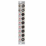
Doepfer A-160-2 Clock/Trigger Divider II Module (silver) (clock modulator/frequency divider synth module)
Cat: 671576 Rel: 29 Nov 17
Enhanced clock divider with multiple dividing factors - 4HP
Notes: Module A-160-2 is an enhanced version of the standard clock divider A-160. The module is a frequency divider for clock/trigger/gate signals, designed to be a source of lower frequencies, particularly for rhythm uses. The Clock input will take any digital signal from, eg. LFO, MIDI sync, or the gate from a MIDI-CV interface. At the outputs, you have access to three sets of seven different sub-divided clock signals, from half the clock frequency down to 1/128. The low/high levels of the output signals are 0V and about +10V.
The A-160-2 also has a reset input. Whenever a reset signal is sensed, all outputs are set to certain levels which depend upon the selected mode.
These are the most important features of the module:
Three different sets of dividing factors, selected by a three-position switch at the front panel:
- Power of two: 2, 4, 8, 16, 32, 64, 128
- Prime numbers: 2, 3, 5, 7, 11, 13, 17
- Integer: 2, 3, 4, 5, 6, 7, 8
Two output modes, selected by a two-position switch at the front panel:
- Gate mode: outputs act like the outputs of typical binary dividers
- Trigger mode: in this mode the outputs are AND-wired with the clock signal (i.e. the clock pulsewidth affects the pulsewidth of the outputs)
- Clock edge type selected by a jumper on the pc board:
- Positive: the rising edge of the clock signal triggers the state change of the outputs
- Negative: the falling edge of the clock signal triggers the state change of the outputs
Reset behaviour by two jumpers on the pc board:
- Level triggered: the level at the Reset input triggers the Reset
- Edge triggered: the edge of the signal at the Reset input triggers the Reset
- Positive: a high level (> 2.5V) or the rising edge at the Reset input triggers the Reset
- Negative: a low level (< 1 V) or the falling edge at the Reset input triggers the Reset
Output polarity selected by a jumper on the pc board:
- Positive: non-inverted outputs
- Negative: all seven outputs are inverted
Width: 4HP / 20mm
Depth: 35mm (Measured from the rear side of the front panel)
Current: +12V: +50mA, -12V: -0mA
… Read moreThe A-160-2 also has a reset input. Whenever a reset signal is sensed, all outputs are set to certain levels which depend upon the selected mode.
These are the most important features of the module:
Three different sets of dividing factors, selected by a three-position switch at the front panel:
- Power of two: 2, 4, 8, 16, 32, 64, 128
- Prime numbers: 2, 3, 5, 7, 11, 13, 17
- Integer: 2, 3, 4, 5, 6, 7, 8
Two output modes, selected by a two-position switch at the front panel:
- Gate mode: outputs act like the outputs of typical binary dividers
- Trigger mode: in this mode the outputs are AND-wired with the clock signal (i.e. the clock pulsewidth affects the pulsewidth of the outputs)
- Clock edge type selected by a jumper on the pc board:
- Positive: the rising edge of the clock signal triggers the state change of the outputs
- Negative: the falling edge of the clock signal triggers the state change of the outputs
Reset behaviour by two jumpers on the pc board:
- Level triggered: the level at the Reset input triggers the Reset
- Edge triggered: the edge of the signal at the Reset input triggers the Reset
- Positive: a high level (> 2.5V) or the rising edge at the Reset input triggers the Reset
- Negative: a low level (< 1 V) or the falling edge at the Reset input triggers the Reset
Output polarity selected by a jumper on the pc board:
- Positive: non-inverted outputs
- Negative: all seven outputs are inverted
Width: 4HP / 20mm
Depth: 35mm (Measured from the rear side of the front panel)
Current: +12V: +50mA, -12V: -0mA
4 in stock $97.50
Click for better price!
or call +44 20 7424 1960
quote 671576
quote 671576
People also bought...
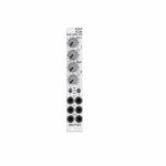
Doepfer A-130-2 Dual Linear/Exponential VCA Slim Line Series Module (dual/stereo/VCA synth module)
Cat: 731940 Rel: 11 Jun 19
Compact two-channel VCA - 4HP
Notes: Module A-130-2 is the slim version of module A-132-3 and offers essentially the same features. But the distances between the controls are smaller and rubberized small-sized knobs are used. In return the front panel has 4 HP only which is half the width of the A-132-3. The module is primarily planned for applications where only limited space is available.
The module is composed of two identical voltage controlled amplifiers (VCA). Each VCA has a manual gain control (also named Initial Gain) and a control voltage input with attenuator. The character of the control scale can be switched to linear or exponential. All inputs and outputs are DC coupled. Consequently the VCAs can be used to process both audio and control voltages (e.g. for voltage control of the level of LFO or envelope signals). The signal input has no attenuator available but is capable to process up to 16Vpp signals (i.e. -8V...+8V) without distortion. For the processing of higher levels an external attenuator (e.g. A-183-1) is recommended.
The amplification range is 0...1. Even with a higher external control voltage the amplification remains at 1 (kind of "amplification clipping" at 1).
Controls (for each of both units):
- Gain: manual gain control (Initial Gain) in the range 0...1
- CV: attenuator for the CV input
- Lin/Exp: switches the VCA characteristic to linear or exponential, in center position the VCA is off (mute function)
Inputs and outputs (for each of both units):
- CV: control voltage input, min. +5V required for max. amplification (1) with CV control fully CW and Gain fully CCW
- In: signal input, max. 16Vpp (+8V...-8V) without distortion
- Out: signal output
… Read moreThe module is composed of two identical voltage controlled amplifiers (VCA). Each VCA has a manual gain control (also named Initial Gain) and a control voltage input with attenuator. The character of the control scale can be switched to linear or exponential. All inputs and outputs are DC coupled. Consequently the VCAs can be used to process both audio and control voltages (e.g. for voltage control of the level of LFO or envelope signals). The signal input has no attenuator available but is capable to process up to 16Vpp signals (i.e. -8V...+8V) without distortion. For the processing of higher levels an external attenuator (e.g. A-183-1) is recommended.
The amplification range is 0...1. Even with a higher external control voltage the amplification remains at 1 (kind of "amplification clipping" at 1).
Controls (for each of both units):
- Gain: manual gain control (Initial Gain) in the range 0...1
- CV: attenuator for the CV input
- Lin/Exp: switches the VCA characteristic to linear or exponential, in center position the VCA is off (mute function)
Inputs and outputs (for each of both units):
- CV: control voltage input, min. +5V required for max. amplification (1) with CV control fully CW and Gain fully CCW
- In: signal input, max. 16Vpp (+8V...-8V) without distortion
- Out: signal output
6 in stock $79.86
Click for better price!
or call +44 20 7424 1960
quote 731940
quote 731940
People also bought...
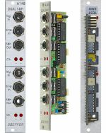
Doepfer A-148 Dual Sample & Hold - Track & Hold Module (silver) (CV modulation/sample & hold/dual/stereo synth module)
Cat: 577745 Rel: 29 Nov 17
Two sample & hold units in one module for generating stepped random voltages or slicing signals
Notes: Module A-148 (Dual S&H) has two identical sample & hold modules, designed to produce 'staircase' voltages. The signal present at the sample input is sampled at a rate set by the signal at the trigger input, and held at that voltage at the S&H output.
The exact shape of the staircase depends on the sort of waveform at the sample input: NOISE or RANDOM signals produce random patterns; an LFO produces rising or falling staircase patterns.
Two LEDs for each S&H indicate the voltage (positive or negative) of the sampled signal.
… Read moreThe exact shape of the staircase depends on the sort of waveform at the sample input: NOISE or RANDOM signals produce random patterns; an LFO produces rising or falling staircase patterns.
Two LEDs for each S&H indicate the voltage (positive or negative) of the sampled signal.
1 in stock $66.38
Click for better price!
or call +44 20 7424 1960
quote 577745
quote 577745
People also bought...
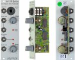
Doepfer A-119 External Input Envelope Follower Module (silver) (external/envelope follower/preamp/controller/comparator synth module)
Cat: 577771 Rel: 29 Nov 17
Envelope follower & pre-amplifier for microphone/line-signals - 8HP
Notes: Module A-119 (External Input / Envelope Follower) is designed to allow external audio signals to be integrated into the System A-100. It comprises a pre-amp, envelope follower, and comparator.
The pre-amp has two inputs: an unbalanced input for line level signals, with a gain factor of from 0 to 20, and a balanced input with a gain factor of from 0 to 500, for insertion of low level signals, for instance from a microphone or electric guitar.
The Envelope Follower reads the signal level of the input, and puts out a proportional voltage as an envelope at its own output.
The comparator generates a gate signal whenever the input goes above an adjustable trigger threshold.
Three LED's help you keep track of overload, the envelope, and the gate signal.
… Read moreThe pre-amp has two inputs: an unbalanced input for line level signals, with a gain factor of from 0 to 20, and a balanced input with a gain factor of from 0 to 500, for insertion of low level signals, for instance from a microphone or electric guitar.
The Envelope Follower reads the signal level of the input, and puts out a proportional voltage as an envelope at its own output.
The comparator generates a gate signal whenever the input goes above an adjustable trigger threshold.
Three LED's help you keep track of overload, the envelope, and the gate signal.
7 in stock $67.41
Click for better price!
or call +44 20 7424 1960
quote 577771
quote 577771
People also bought...
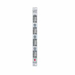
Doepfer A-183-9 Quad USB Power Supply Module (power/quad/utility synth module)
Cat: 711015 Rel: 29 Nov 18
Simple power supply for up to four devices - 2HP
Notes: Module A-183-9 is a simple power supply for up to four devices which can be powered via USB (e.g. keyboards, smartphones). An LED shows is the +5V are present.
The module has no USB function but provides only the +5V supply for USB devices.
A control LED shows if the +5V are present.
Note: The module requires an A-100 case with built in power supply A-100PSU3. Only this A-100 supply has the required +5V available. We do not recommend the usage of an older A-100 case with A-100PSU2 as this would require the +5V adapter A-100AD5 and the max. current would be limited to 100mA.
… Read moreThe module has no USB function but provides only the +5V supply for USB devices.
A control LED shows if the +5V are present.
Note: The module requires an A-100 case with built in power supply A-100PSU3. Only this A-100 supply has the required +5V available. We do not recommend the usage of an older A-100 case with A-100PSU2 as this would require the +5V adapter A-100AD5 and the max. current would be limited to 100mA.
4 in stock $51.85
Click for better price!
or call +44 20 7424 1960
quote 711015
quote 711015
People also bought...
Doepfer A-147-2 Voltage Controlled Delayed Low Frequency Oscillator Module (silver) (envelope generator/LFO/VCA/CV modulation synth module)
Cat: 671585 Rel: 29 Nov 17
Module consisting of voltage-controlled low frequency oscillator (LFO) & voltage controlled amplifier (VCA) - 8HP
Notes: Module A-147-2 is the successor of the VCLFO A-147 but offers much more features than the predecessor. The module is made of these sub-units:
- VCLFO: voltage controlled low frequency oscillator
- VCA: voltage controlled amplifier, switchable to voltage controlled polarizer
- VC delay unit: voltage controlled linear attack envelope (only one parameter: attack) for delayed LFO operation in combination with the VCA (e.g. delayed vibrato/tremolo)
LFO: The voltage controlled LFO has the waveforms Triangle, Sine, Sawtooth and Rectangle available and features a Reset/Sync input. Triangle/Sine and Rectangle are displayed by means of dual-colour LEDs (probably red/green), Sawtooth has a unicolor LED available (probably blue). The output levels are about -4V...+4V for Triangle, Sine and Rectangle. The Sawtooth level is about 0...+8V.
The CV control can be switched to attenuator or polarizer ("CV Mode" switch). In polarizer mode the CV inputs affects the frequency in the reverse manner when the CV control is left from the centre position. In the centre position CV has no effect and right from the centre the control works like a normal attenuator. The frequency range (without external CV) is from about 0,005 Hz (i.e. about 3 minutes per period) to 200 Hz (with external CV max. frequency about 1kHz). In addition a ultra-low mode can be activated by means of an internal jumper. When the ultra-low jumper is set a fixed voltage is connected to the switching contact of the "LFO CV" socket. In polarizer mode of the CV control that way extremely low frequencies (up to one hour period and more) are possible. For this a jumper has to be installed on the pin header JP6. In the factory a dummy jumper is installed on the pin header JP7 "Dummy". JP7 has no function and is used only for "parking" of the jumper. Simply remove the jumper from JP7 and plug it on JP6. JP6 is located behind the CV control.
VCA: This is a linear VCA that can be switched to "normal" VCA (i.e. kind of a voltage controlled attenuator) or voltage controlled polarizer ("VCA Mode" switch). In the "normal" VCA mode amplification +1 is achieved with about +5V control voltage. In polarizer mode the amplification ranges from about -0.5 (i.e. inverted signal with about 50% level) with 0V CV to +0.5 (i.e. non-inverted signal with about 50% level) with +5V CV. With about +2.5V CV the signal is suppressed. Details about the functioning of a voltage controlled polarizer can be found in the description of the module A-133. In this mode the VCA can be treated also a DC coupled ring modulator (similar to A-114).
The VCA of the A-147-2 has three sockets available: "In" (signal input), "Out" (signal output) and "CV" (control voltage input).
The Triangle Output of the LFO is normalled to the VCA signal input by means of the switching contact of the "VCA In" socket. If another LFO waveform (or any other signal) should be processed by the VCA the corresponding signal has to be patched to the "VCA In" socket. The VCA can be used also independently from the LFO and the Delay CV. In this case the VCA sockets In, Out and CV have to be patched accordingly. The VCA can be used also as waveshaper for the LFO signals (e.g. by patching VCA In and VCA CV to different LFO signals, if necessary via attenuator A-183-1 or offset generator/attenuator A-183-2).
Attack/Delay: The third sub-unit of the module is a simple, voltage controlled envelope generator that has only the parameter "Delay" (or Attack) available. This unit generates a linear increasing voltage that starts from 0V after each Delay Reset until it reaches about +5V. Then the voltage remains at +5V until the next Delay Reset occurs. The inclination or gradient is controlled by the manual Delay control and the Delay control voltage ("Delay CV" input). The waveform is linear, the control scale is exponential. The output voltage is displayed by a green LED and available at the "Delay Out" socket.
The manual Delay control ranges - without external "Delay CV" - from about 5ms (fully CW) up to 2 minutes (fully CCW). By means of an external voltage applied to the "Delay CV" socket this range can be extended. A rising CV shortens the delay time (behaviour like a VCO)!
The Delay output voltage ranges from about 0V to +5V. The rising edge of the gate, clock or trigger signal applied to the "Delay Reset" sockets resets the Delay output voltage to 0 V.
"Delay Out" is normalled to the VCA CV input by means of the switching contact of the "VCA CV" socket and consequently controls the Triangle level provided that no other patch is made. A typical example is the usage of a Gate signal (e.g. from a USB/Midi-to-CV/Gate interface) as Delay Reset. That way a delayed vibrato or tremolo can be realized if the VCA output is patched to the frequency CV input of a VCO (or VCF), or the CV input of a VCA.
… Read more- VCLFO: voltage controlled low frequency oscillator
- VCA: voltage controlled amplifier, switchable to voltage controlled polarizer
- VC delay unit: voltage controlled linear attack envelope (only one parameter: attack) for delayed LFO operation in combination with the VCA (e.g. delayed vibrato/tremolo)
LFO: The voltage controlled LFO has the waveforms Triangle, Sine, Sawtooth and Rectangle available and features a Reset/Sync input. Triangle/Sine and Rectangle are displayed by means of dual-colour LEDs (probably red/green), Sawtooth has a unicolor LED available (probably blue). The output levels are about -4V...+4V for Triangle, Sine and Rectangle. The Sawtooth level is about 0...+8V.
The CV control can be switched to attenuator or polarizer ("CV Mode" switch). In polarizer mode the CV inputs affects the frequency in the reverse manner when the CV control is left from the centre position. In the centre position CV has no effect and right from the centre the control works like a normal attenuator. The frequency range (without external CV) is from about 0,005 Hz (i.e. about 3 minutes per period) to 200 Hz (with external CV max. frequency about 1kHz). In addition a ultra-low mode can be activated by means of an internal jumper. When the ultra-low jumper is set a fixed voltage is connected to the switching contact of the "LFO CV" socket. In polarizer mode of the CV control that way extremely low frequencies (up to one hour period and more) are possible. For this a jumper has to be installed on the pin header JP6. In the factory a dummy jumper is installed on the pin header JP7 "Dummy". JP7 has no function and is used only for "parking" of the jumper. Simply remove the jumper from JP7 and plug it on JP6. JP6 is located behind the CV control.
VCA: This is a linear VCA that can be switched to "normal" VCA (i.e. kind of a voltage controlled attenuator) or voltage controlled polarizer ("VCA Mode" switch). In the "normal" VCA mode amplification +1 is achieved with about +5V control voltage. In polarizer mode the amplification ranges from about -0.5 (i.e. inverted signal with about 50% level) with 0V CV to +0.5 (i.e. non-inverted signal with about 50% level) with +5V CV. With about +2.5V CV the signal is suppressed. Details about the functioning of a voltage controlled polarizer can be found in the description of the module A-133. In this mode the VCA can be treated also a DC coupled ring modulator (similar to A-114).
The VCA of the A-147-2 has three sockets available: "In" (signal input), "Out" (signal output) and "CV" (control voltage input).
The Triangle Output of the LFO is normalled to the VCA signal input by means of the switching contact of the "VCA In" socket. If another LFO waveform (or any other signal) should be processed by the VCA the corresponding signal has to be patched to the "VCA In" socket. The VCA can be used also independently from the LFO and the Delay CV. In this case the VCA sockets In, Out and CV have to be patched accordingly. The VCA can be used also as waveshaper for the LFO signals (e.g. by patching VCA In and VCA CV to different LFO signals, if necessary via attenuator A-183-1 or offset generator/attenuator A-183-2).
Attack/Delay: The third sub-unit of the module is a simple, voltage controlled envelope generator that has only the parameter "Delay" (or Attack) available. This unit generates a linear increasing voltage that starts from 0V after each Delay Reset until it reaches about +5V. Then the voltage remains at +5V until the next Delay Reset occurs. The inclination or gradient is controlled by the manual Delay control and the Delay control voltage ("Delay CV" input). The waveform is linear, the control scale is exponential. The output voltage is displayed by a green LED and available at the "Delay Out" socket.
The manual Delay control ranges - without external "Delay CV" - from about 5ms (fully CW) up to 2 minutes (fully CCW). By means of an external voltage applied to the "Delay CV" socket this range can be extended. A rising CV shortens the delay time (behaviour like a VCO)!
The Delay output voltage ranges from about 0V to +5V. The rising edge of the gate, clock or trigger signal applied to the "Delay Reset" sockets resets the Delay output voltage to 0 V.
"Delay Out" is normalled to the VCA CV input by means of the switching contact of the "VCA CV" socket and consequently controls the Triangle level provided that no other patch is made. A typical example is the usage of a Gate signal (e.g. from a USB/Midi-to-CV/Gate interface) as Delay Reset. That way a delayed vibrato or tremolo can be realized if the VCA output is patched to the frequency CV input of a VCO (or VCF), or the CV input of a VCA.
1 in stock $116.17
People also bought...
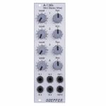
Doepfer A-138s Mini Stereo Mixer Module (silver) (mixer/panning/dual/stereo/quad synth module)
Cat: 671589 Rel: 29 Nov 17
Four-channel stereo mixer - 8HP
Notes: A-138s is a simple but useful 4-in-2 mixing tool. It has four inputs available. Each input is equipped with an attenuator (Level) and a panning control that is used to distribute the signal to the left and right output. Beyond stereo mixing it is equally suited to create variable parallel routings. For example: Any of the four inputs may be routed in variable intensity to feed two filters.
You may regard the A-138s as a smaller version of the A-138m Matrix Mixer.
Inputs and outputs are DC coupled, i.e. the module can be used for the mixing of control signals too.
- 3U Eurorack module, 8 HP wide, 30 mm in depth
- Power consumption: 10 mA at +12 V and 10 mA at -12 V
… Read moreYou may regard the A-138s as a smaller version of the A-138m Matrix Mixer.
Inputs and outputs are DC coupled, i.e. the module can be used for the mixing of control signals too.
- 3U Eurorack module, 8 HP wide, 30 mm in depth
- Power consumption: 10 mA at +12 V and 10 mA at -12 V
1 in stock $77.78
People also bought...
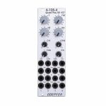
Doepfer A-105-4 Quad Poly SSM VCF Polyphonic Filter Module (filter/quad synth module)
Cat: 676691 Rel: 21 Sep 18
Polyphonic filter with four identical 24dB Lowpass filters 8HP
Notes: A-105-4 is our first polyphonic filter and contains four
identical 24dB Lowpass filters (SSM2044 type). It has
available common manual controls and CV inputs with
attenuators for these parameters:
Frequency (F)
Frequency Modulation Intensity (FM)
Resonance (Q)
Audio Input Level (L)
Each filter has available a separate FM input as well as an Audio Input and Output. The FM input is typically connected to the output of the associated envelope generator (e.g. A-141-4).
The envelope amount for all four filters is controlled by the FM knob and the CVFM input by means of four built-in VCAs, which are controlled by the FM control and CVFM input. This allows also voltage control of the envelope amounts.
In addition common frequency modulation for all filters is possible (e.g. by an LFO). For this the CVF input with attenuator can be used. The range of the audio input level control (L) allows also clipping/distortion with typical A-100 audio levels
(e.g. from A-111-4) at the filter inputs. Even this parameter is voltage controllable as well as the resonance (Q).
Application: polyphonic patches (four VCFs with same parameters).
… Read moreidentical 24dB Lowpass filters (SSM2044 type). It has
available common manual controls and CV inputs with
attenuators for these parameters:
Frequency (F)
Frequency Modulation Intensity (FM)
Resonance (Q)
Audio Input Level (L)
Each filter has available a separate FM input as well as an Audio Input and Output. The FM input is typically connected to the output of the associated envelope generator (e.g. A-141-4).
The envelope amount for all four filters is controlled by the FM knob and the CVFM input by means of four built-in VCAs, which are controlled by the FM control and CVFM input. This allows also voltage control of the envelope amounts.
In addition common frequency modulation for all filters is possible (e.g. by an LFO). For this the CVF input with attenuator can be used. The range of the audio input level control (L) allows also clipping/distortion with typical A-100 audio levels
(e.g. from A-111-4) at the filter inputs. Even this parameter is voltage controllable as well as the resonance (Q).
Application: polyphonic patches (four VCFs with same parameters).
! low stock $188.77
People also bought...
Doepfer A-140-2 Dual Micro ADSR Module (silver) (dual/stereo/envelope generator synth module)
Cat: 684450 Rel: 18 Jul 18
Dual ADSR envelope generator - 8HP
Notes: Module A-140-2 contains two ADSR type envelope generators behind a front panel with 8 HP only.
Each ADSR provides these controls and in/outputs:
- LED (displays the envelope output)
- A: manual Attack control
- D: manual Decay control
- S: manual Sustain control
- R: manual Release control
- Gate Input
- Retrigger Input
- CVT Input with attenuator (CVT = CV Time)
- Envelope Output 1
- Envelope Output 2
The output voltage range for each envelope is 0 - 10V. The time range of Attack/Decay/Release is about 1ms to 30s.
By means of internal jumpers one can select which time parameters are controlled by the CVT input (e.g. D only or D+R or A+D+R) and in which direction (i.e. if an increasing CVT shortens or stretches the time parameter in question).
Socket CVT can be normalled to an internal fixed voltage (i.e. the switching contact is connected to an internal fixed voltage). That way it's possible to change all time parameters simultaneously by means of the CVT control.
Another jumper is used to set output 2 to normal or inverted envelope.
And another jumper is used for the normalling of Gate 2 to Gate 1 (i.e. ADSR#2 is also triggered by Gate 1).
Two more jumpers are used for the optional bus access to the gate signal of the bus for each ADSR. Changing the positions of the mentioned jumpers allows to modify the factory settings.
… Read moreEach ADSR provides these controls and in/outputs:
- LED (displays the envelope output)
- A: manual Attack control
- D: manual Decay control
- S: manual Sustain control
- R: manual Release control
- Gate Input
- Retrigger Input
- CVT Input with attenuator (CVT = CV Time)
- Envelope Output 1
- Envelope Output 2
The output voltage range for each envelope is 0 - 10V. The time range of Attack/Decay/Release is about 1ms to 30s.
By means of internal jumpers one can select which time parameters are controlled by the CVT input (e.g. D only or D+R or A+D+R) and in which direction (i.e. if an increasing CVT shortens or stretches the time parameter in question).
Socket CVT can be normalled to an internal fixed voltage (i.e. the switching contact is connected to an internal fixed voltage). That way it's possible to change all time parameters simultaneously by means of the CVT control.
Another jumper is used to set output 2 to normal or inverted envelope.
And another jumper is used for the normalling of Gate 2 to Gate 1 (i.e. ADSR#2 is also triggered by Gate 1).
Two more jumpers are used for the optional bus access to the gate signal of the bus for each ADSR. Changing the positions of the mentioned jumpers allows to modify the factory settings.
1 in stock $138.98
People also bought...
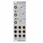
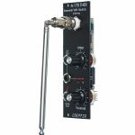
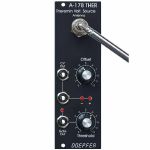
Doepfer A-178v Theremin Control Voltage Source Vintage Edition Module (black) (controller/CV modulation/utility synth module)
Cat: 852800 Rel: 05 Jan 22
Theremin module for generating a variable control voltage by approaching/removing hand to/from an antenna.
Notes: Theremin module for generating a variable control voltage by approaching/removing hand to/from an antenna.
The distance range is about 30 cm. Additionally the module is equipped with a Gate output with adjustable threshold level. To simulate the original Theremin two A-178, a VCO (e.g. A-110) and a linear VCA (e.g. A-130 or A-132) are required. But of course the A-178 can be used to control other functions in the A-100 (e.g. filter frequency, modulation depth and/or speed, tempo, attack/decay time and so on).
The CV output voltage of the A-178 can range - according to the setting of the front panel controls - from -10V...+10V.
The gate output switches from 0V to about +10V.
Power consumption: 60mA at +12V and 20mA at -12V
Depth: 40mm
HP : 8
… Read moreThe distance range is about 30 cm. Additionally the module is equipped with a Gate output with adjustable threshold level. To simulate the original Theremin two A-178, a VCO (e.g. A-110) and a linear VCA (e.g. A-130 or A-132) are required. But of course the A-178 can be used to control other functions in the A-100 (e.g. filter frequency, modulation depth and/or speed, tempo, attack/decay time and so on).
The CV output voltage of the A-178 can range - according to the setting of the front panel controls - from -10V...+10V.
The gate output switches from 0V to about +10V.
Power consumption: 60mA at +12V and 20mA at -12V
Depth: 40mm
HP : 8
1 in stock $96.45
People also bought...
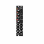
Doepfer A-145-4v Quad LFO Low Frequency Oscillator Vintage Edition Module (black) (quad/LFO synth module)
Cat: 760210 Rel: 01 Apr 20
Notes: Module A-145-4 is a simple quad LFO (Low Frequency Oscillator). Not a very "exciting" module, just a bread-and-butter device and a simple demon for work. Virtually in every modular system several LFOs are required for modulation purposes. The module contains four simple LFOs with the waveforms triangle and rectangle. A dual colour LED (red = positive / yellow = negative output voltage) indicates the triangle output of each LFO. The frequency range can be chosen for each LFO individually by means of a jumper between about 50 Hz ... 0.04 Hz (about 20 seconds, jumper removed) and about 2Hz ... 0.002 (about 8 minutes, jumper installed).
The module can be treated as a slimmed version of the quad LFO A-143-3 as it has similar features available. But the distances between the controls are smaller and rubberized small-sized knobs are used. In return the front panel has 4 HP only which is less than one third of the A-143-3. The module is primarily planned for applications where only limited space is available. The functional difference compared to the A-143-3 are the missing sawtooth outputs and frequency range switches.
… Read moreThe module can be treated as a slimmed version of the quad LFO A-143-3 as it has similar features available. But the distances between the controls are smaller and rubberized small-sized knobs are used. In return the front panel has 4 HP only which is less than one third of the A-143-3. The module is primarily planned for applications where only limited space is available. The functional difference compared to the A-143-3 are the missing sawtooth outputs and frequency range switches.
2 in stock $89.20
Click for better price!
or call +44 20 7424 1960
quote 760210
quote 760210
People also bought...
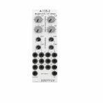
Doepfer A-135-2 Quad VCA & Voltage Controller Mixer Module (silver) (mixer/quad/VCA synth module)
Cat: 714704 Rel: 22 Jan 19
Compact voltage-controlled four-channel audio mixer - 8HP
Notes: A-135-2 is a miniature version of the A-135-1. Behind a front panel with 8 HP only four linear VCAs (voltage controlled amplifiers) and a voltage controlled mixer based on the VCAs are available.
Controls, In/Outputs and Functions of each VCA:
- Level (manual control of the VCA amplification), small rubberized knob (L1...L4)
- Control voltage input with associated attenuator (CV1...CV4), for the full VCA control range about 0...+5V control voltage are required (attenuator fully clockwise), for higher control voltages the attenuator is used, the attenuators are without knobs, just plastic shafts with white marker
- Signal Input
- Signal Output
- All inputs and outputs are DC coupled. Consequently the VCAs can be used to process both audio and control voltages (e.g. to control the level of LFOs or envelopes)
- The signal input is not equipped with an attenuator. But the VCAs can process all signals up to 15Vpp / -7.5...+7.5V without clipping. In case of higher levels an external attenuator is required (e.g. A-183-1).
- The available amplification range is 0...1, the maximal amplification is 1 (i.e. it "clips" and remains at 1 even if the control voltage goes beyond the value that corresponds to amplification 1)
Functions of the voltage controlled mixers:
- Two outputs ("Selected" and "All")
- Selected output: the ouput if a VCA is removed from this sum signal when a plug is inserted into the corresponding VCA output.
- All output: sum of all VCA outputs, regardless of inserted plugs into the VCA outputs
- The maximal amplification is about 0.6 to avoid clipping at the mixer outputs (otherwise the outputs may distort with 15Vpp signals at each signal input and full amplifications)
Special functions of the voltage controlled mixers (selectable by internal jumpers):
- Dual Stereo VCA: In this case the control unit of VCA1 (L1 + CV1) affects also VCA3 and the control unit of VCA2 (L2 + CV2) affects also VCA4, the control units of VCA2 and VCA4 are out of operation
- Quad VCA: In this case the control unit of VCA1 (L1 + CV1) affects all four VCAs. The control units of VCA2, VCA3 and VCA4 are out of operation. In this mode the module has the same function as module A-132-2. That's why module A-132-2 will be discontinued.
- Normalling of the signal inputs: by means of internal jumpers signal input 1 can be normalled to signal input 2, signal input 2 to signal input 3 and signal input 3 to signal input In 4. That way the same input signal can be distributed to four different channels by means of control voltages (e.g. quadrophonic distribution of audio signals). Suitable control voltage sources are e.g. A-144 (Morphing Controller) or A-143-9 (Quadrature LFO).
… Read moreControls, In/Outputs and Functions of each VCA:
- Level (manual control of the VCA amplification), small rubberized knob (L1...L4)
- Control voltage input with associated attenuator (CV1...CV4), for the full VCA control range about 0...+5V control voltage are required (attenuator fully clockwise), for higher control voltages the attenuator is used, the attenuators are without knobs, just plastic shafts with white marker
- Signal Input
- Signal Output
- All inputs and outputs are DC coupled. Consequently the VCAs can be used to process both audio and control voltages (e.g. to control the level of LFOs or envelopes)
- The signal input is not equipped with an attenuator. But the VCAs can process all signals up to 15Vpp / -7.5...+7.5V without clipping. In case of higher levels an external attenuator is required (e.g. A-183-1).
- The available amplification range is 0...1, the maximal amplification is 1 (i.e. it "clips" and remains at 1 even if the control voltage goes beyond the value that corresponds to amplification 1)
Functions of the voltage controlled mixers:
- Two outputs ("Selected" and "All")
- Selected output: the ouput if a VCA is removed from this sum signal when a plug is inserted into the corresponding VCA output.
- All output: sum of all VCA outputs, regardless of inserted plugs into the VCA outputs
- The maximal amplification is about 0.6 to avoid clipping at the mixer outputs (otherwise the outputs may distort with 15Vpp signals at each signal input and full amplifications)
Special functions of the voltage controlled mixers (selectable by internal jumpers):
- Dual Stereo VCA: In this case the control unit of VCA1 (L1 + CV1) affects also VCA3 and the control unit of VCA2 (L2 + CV2) affects also VCA4, the control units of VCA2 and VCA4 are out of operation
- Quad VCA: In this case the control unit of VCA1 (L1 + CV1) affects all four VCAs. The control units of VCA2, VCA3 and VCA4 are out of operation. In this mode the module has the same function as module A-132-2. That's why module A-132-2 will be discontinued.
- Normalling of the signal inputs: by means of internal jumpers signal input 1 can be normalled to signal input 2, signal input 2 to signal input 3 and signal input 3 to signal input In 4. That way the same input signal can be distributed to four different channels by means of control voltages (e.g. quadrophonic distribution of audio signals). Suitable control voltage sources are e.g. A-144 (Morphing Controller) or A-143-9 (Quadrature LFO).
1 in stock $123.42
People also bought...
Doepfer A-138d Crossfader/FX Insert Module (external/mixer synth module)
Cat: 716947 Rel: 29 Jan 19
Crossfader for two different A-100 signals, plus insert for external effects
Notes: The A-138d primarily is used for crossfading between two modular signals. On the other hand you can used it for inserting stompboxes or other effects into your modular system. Both the inputs and the mix output are available twice, like a mini-multiples e.g. for using the input signal also for other applications, kind of like a Thru.
Crossfader: With the crossfading control CF you blend manually between the inputs In 1 and In 2. The Mute switch allows for muting one of the two signals, independent on the crossfader position.
Effect insert: The signal at input In1 is emitted at the FX Send output and can be attenuated with the Atten. control because the modular system works with much higher levels.
The effect unit's output is inserted to the FX Return input socket and its level can be boosted with the Amp. control. The processed signal is available at the bottom in 2 socket.
Use the CF control to blend between the original signal and the effect signal and to mute switch for quick muting e.g. of the effect return signal.
… Read moreCrossfader: With the crossfading control CF you blend manually between the inputs In 1 and In 2. The Mute switch allows for muting one of the two signals, independent on the crossfader position.
Effect insert: The signal at input In1 is emitted at the FX Send output and can be attenuated with the Atten. control because the modular system works with much higher levels.
The effect unit's output is inserted to the FX Return input socket and its level can be boosted with the Amp. control. The processed signal is available at the bottom in 2 socket.
Use the CF control to blend between the original signal and the effect signal and to mute switch for quick muting e.g. of the effect return signal.
1 in stock $68.45
People also bought...
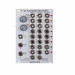
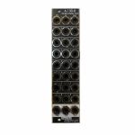
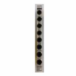
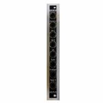
Doepfer A-152 Voltaged Addressed Track & Hold/Switch Module (switch/clock modulator/logic/sample & hold synth module)
Cat: 745781 Rel: 09 Sep 19
Complex switch/multiplexer unit - 16HP
Notes: Module A152 is a very useful switching and T&H module. It combines a voltage addressed 1-to-8 multiplexer and 8 fold T&H that can be used as kind of an analogue shift register too. The active in/output is displayed by a LED. The digital output of the currently addressed step outputs "high". The remaining digital outputs are low.
Instead of voltage control even clock/reset controlled addressing of the active step is possible. The rising edge of each clock signal causes an advance to the next state. The rising edge of the reset signal resets to step 1.
The sum of the voltages coming from the manual Address control and the CV input define the currently addressed step of the 3 sub-devices. If the module is controlled by clock and reset the control voltage has to remain unchanged as the CV control has priority over the clock/reset control (e.g. simply turn the CV control fully counter-clockwise and do not touch the Address control knob).
Sub-device #1 is the bidirectional 8-fold multiplexer (kind of an electronical 8-fold rotary switch). Bidirectional means that it works into both directions like a mechanical rotary switch: the common socket may work as an output that is connected to one of the 8 inputs that are e.g. connected to modulation or audio sources. But the common socket may even function as input. In this case the signal applied to the common socket is output to the currently addressed single socket. The voltage range of the in/outputs to be switched is the full A-100 voltage range -12V....+12V. All A-100 signals can be switched without any restrictions.
Sub-device #2 is the addressed 8-fold T&H. The signal at the common T&H input is connected to the addressed T&H output. As soon as a new output is addressed the last voltage is stored at the output (Track&Hold function). The T&H section of the A-152 allows the emulation of the "toggling T&H" function of the Buchla module 266 "Source of Uncertainty". Only the first two T&H outputs of the A-152 are required for this application. This unit can be used also as kind of an analogue (shift) register. The difference to a "real" analogue shift register is that the sampled output voltages are not shifted to the next output but remain allocated to the same output. But in some cases (e.g. controlling the pitch of 3 VCOs by 3 output voltages of the A-152) the result is the same.
Sub-device #3 is the digital output section. The digital output of the currently addressed turns to "high". All other digital outputs are low. The digital outputs can be used to trigger e.g. envelope generators or to control the reset input in the clocked mode to reduce the number of addressed stages.
… Read moreInstead of voltage control even clock/reset controlled addressing of the active step is possible. The rising edge of each clock signal causes an advance to the next state. The rising edge of the reset signal resets to step 1.
The sum of the voltages coming from the manual Address control and the CV input define the currently addressed step of the 3 sub-devices. If the module is controlled by clock and reset the control voltage has to remain unchanged as the CV control has priority over the clock/reset control (e.g. simply turn the CV control fully counter-clockwise and do not touch the Address control knob).
Sub-device #1 is the bidirectional 8-fold multiplexer (kind of an electronical 8-fold rotary switch). Bidirectional means that it works into both directions like a mechanical rotary switch: the common socket may work as an output that is connected to one of the 8 inputs that are e.g. connected to modulation or audio sources. But the common socket may even function as input. In this case the signal applied to the common socket is output to the currently addressed single socket. The voltage range of the in/outputs to be switched is the full A-100 voltage range -12V....+12V. All A-100 signals can be switched without any restrictions.
Sub-device #2 is the addressed 8-fold T&H. The signal at the common T&H input is connected to the addressed T&H output. As soon as a new output is addressed the last voltage is stored at the output (Track&Hold function). The T&H section of the A-152 allows the emulation of the "toggling T&H" function of the Buchla module 266 "Source of Uncertainty". Only the first two T&H outputs of the A-152 are required for this application. This unit can be used also as kind of an analogue (shift) register. The difference to a "real" analogue shift register is that the sampled output voltages are not shifted to the next output but remain allocated to the same output. But in some cases (e.g. controlling the pitch of 3 VCOs by 3 output voltages of the A-152) the result is the same.
Sub-device #3 is the digital output section. The digital output of the currently addressed turns to "high". All other digital outputs are low. The digital outputs can be used to trigger e.g. envelope generators or to control the reset input in the clocked mode to reduce the number of addressed stages.
1 in stock $140.02
People also bought...
Doepfer A-180-2v Passive Multiple vintage Edition Module (black) (dual/stereo/multiple synth module)
Cat: 751717 Rel: 23 Oct 19
Passive multi-port distributor - 2HP
Notes: 2HP narrow version of the A-180 multiples module. It is a passive signal splitter suitable for audio or CVs. Two sets of four jacks are interconnected, by placing a solder bridge you can connect all eight jacks.
… Read more 1 in stock $43.55
Click for better price!
or call +44 20 7424 1960
quote 751717
quote 751717
People also bought...
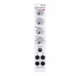
Doepfer A-101-8 Photo Phasing 8-Stage Phase Shifter Module (silver) (phase shifter/effect synth module)
Cat: 945411 Rel: 13 Jun 23
An eight stage phase shifter module in 4HP.
Notes: Module A-101-8 is a 8-stage phase shifter which uses light-sensitive resistors (LDR) and is a replica of the Compact Phasing A manufactured by the company Schulte in the seventies. The actual phasing circuit is identical to the historic model. Only the illumination control of the LDRs is different: the A-101-8 uses LEDs to illuminate the LDRs, the historic model used incandescent miniature lamps. And the A-101-8 has no built-in LFO but can be controlled by any external control voltage source (e.g. LFO, ADSR, random, Theremin, ribbon controller, sequencer, midi). The phasing offset (i.e. the base value for the phase shifting) and the modulation depth of the external control signal can be adjusted separately. The Compact Phasing A had no offset control but only a depth control for the built-in LFO. Feedback and mixing ratio of the output signal are set by two controls. The audio input is equipped with an attenuator. The module has two audio outputs available (same as the historic model) and a visual display of the phase shifting.
The module has these controls and in/outputs available:
Control Man. : manual control of the phase shift offset (base value)
Control CV: attenuator for the signal applied to the CV socket
Control Feedb.: Feedback or Resonance (similar function as filter resonance/feedback/emphasis)
Control Mix: sets the mixing ratio between original and phase shift signal appearing at output 1
fully CCW: only the modified input signal appears at output 1 (see note below *)
center: a mixture between the modified input signal and the phase shift signal appears at output 1, that's the standard position for the classical phasing effect
fully CW: the pure phase shifted signal appears at output 1 (e.g. for vibrato effects)
Control Input Level: attenuator for signal applied to the In socket
Socket In: audio input
Socket CV: control voltage input
Socket Out 1: audio output 1 (mix signal)
Socket Out 2: audio output 2 (modified input signal)
LED: visual control of the phase shift
The module has some peculiarities (same as the historic model):
The input signal is processed at first by a pre-stage which outputs a "modified" input signal (*). This signal is not processed by the phase shift stages but is affected by the feedback setting. Only when feedback is set to zero this signal is identical to the input signal. Otherwise it contains feedback components.
This signal is output on socket Out 2.
When both output sockets Out 1 and Out 2 are used as stereo channels one obtains a spatial stereo sound effect.
The same signals is also used for the CCW position of the mix control. With mix control fully CCW the unmodified signal appears only if the feedback control is set to zero. Otherwise it contains feedback components.
The historic model had two audio inputs: one 5-pin DIN socket and a 1/4" jack socket. The DIN socket was intended for high-level line signals. When the 1/4" jack socket was used the amplification of the pre-stage increased by about 100. The 1/4" jack socket was intended for low level signals (e.g. electric guitars or microphones). For this feature the A-101-8 has an internal jumper that can be used to increase the amplification. As long as the module is used within the A-100 system usually the lower amplification is used to avoid distortion.
The 8 photo resistors and LEDs are assembled within an small lighproof box. In addition the pc boards are made of lighproof black material to avoid interfering light from other modules or the bus board.
Dimensions
4 HP
45 mm deep
Current Draw
30 mA +12V
30 mA -12V
… Read moreThe module has these controls and in/outputs available:
Control Man. : manual control of the phase shift offset (base value)
Control CV: attenuator for the signal applied to the CV socket
Control Feedb.: Feedback or Resonance (similar function as filter resonance/feedback/emphasis)
Control Mix: sets the mixing ratio between original and phase shift signal appearing at output 1
fully CCW: only the modified input signal appears at output 1 (see note below *)
center: a mixture between the modified input signal and the phase shift signal appears at output 1, that's the standard position for the classical phasing effect
fully CW: the pure phase shifted signal appears at output 1 (e.g. for vibrato effects)
Control Input Level: attenuator for signal applied to the In socket
Socket In: audio input
Socket CV: control voltage input
Socket Out 1: audio output 1 (mix signal)
Socket Out 2: audio output 2 (modified input signal)
LED: visual control of the phase shift
The module has some peculiarities (same as the historic model):
The input signal is processed at first by a pre-stage which outputs a "modified" input signal (*). This signal is not processed by the phase shift stages but is affected by the feedback setting. Only when feedback is set to zero this signal is identical to the input signal. Otherwise it contains feedback components.
This signal is output on socket Out 2.
When both output sockets Out 1 and Out 2 are used as stereo channels one obtains a spatial stereo sound effect.
The same signals is also used for the CCW position of the mix control. With mix control fully CCW the unmodified signal appears only if the feedback control is set to zero. Otherwise it contains feedback components.
The historic model had two audio inputs: one 5-pin DIN socket and a 1/4" jack socket. The DIN socket was intended for high-level line signals. When the 1/4" jack socket was used the amplification of the pre-stage increased by about 100. The 1/4" jack socket was intended for low level signals (e.g. electric guitars or microphones). For this feature the A-101-8 has an internal jumper that can be used to increase the amplification. As long as the module is used within the A-100 system usually the lower amplification is used to avoid distortion.
The 8 photo resistors and LEDs are assembled within an small lighproof box. In addition the pc boards are made of lighproof black material to avoid interfering light from other modules or the bus board.
Dimensions
4 HP
45 mm deep
Current Draw
30 mA +12V
30 mA -12V
8 in stock $123.18
Click for better price!
or call +44 20 7424 1960
quote 945411
quote 945411
People also bought...
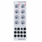
Notes: Module A-130-4 contains four linear VCAs with a common level control section for all four VCAs. It can be used for all applications of simultaneous amplitude/level control of up to four different audio or CV signals. A-130-4 is the replacement of the no longer available module A-132-2. Compared to the A-132-2 the width has been reduced from 8HP to 4HP.
The module has these controls and in/outputs available:
Control Man.: manual control of the amplification
Control CV: attenuator for the control voltage applied to socket CVo socket Input 1
Sockets In 1...4: VCA inputs 1...4
Sockets Out 1...4: VCA outputs 1...4
Application examples:
simultaneous amplitude/level control of up to four different audio or CV signals
polyphonic application 1: simultaneous control of the frequency modulation depth of 4 VCOs (Quad-LFO A-145-4 or Quad-VCLFO A-147-5 > A-130-4 > FM inputs A-111-4)
polyphonic application 2: simultaneous control of the pulsewidth modulation depth of 4 VCOs (Quad-LFO A-145-4 or Quad-VCLFO A-147-5 > A-130-4 > PWM inputs A-111-4)
simultaneous control of quadrophonic signals
Technical notes:
The maximum amplification for each VCA is about 1 ("Man." control fully CW). Even with an external control voltage applied to the CV input the maximum amplification is limited to 1.
The module is equipped with two internal connectors (pin headers with 4 pins each). Pin header #1 can be used to normalize the four inputs to other modules (e.g. Quad LFO A-145-4 or A-147-5, Quad ADSR A-143-2). Pin header #2 can be used to connect the four outputs to other modules.
The max. level at the VCA inputs without clipping/distortion is about 20Vpp or +/-10V.
Dimensions
4 HP
45 mm deep
… Read moreThe module has these controls and in/outputs available:
Control Man.: manual control of the amplification
Control CV: attenuator for the control voltage applied to socket CVo socket Input 1
Sockets In 1...4: VCA inputs 1...4
Sockets Out 1...4: VCA outputs 1...4
Application examples:
simultaneous amplitude/level control of up to four different audio or CV signals
polyphonic application 1: simultaneous control of the frequency modulation depth of 4 VCOs (Quad-LFO A-145-4 or Quad-VCLFO A-147-5 > A-130-4 > FM inputs A-111-4)
polyphonic application 2: simultaneous control of the pulsewidth modulation depth of 4 VCOs (Quad-LFO A-145-4 or Quad-VCLFO A-147-5 > A-130-4 > PWM inputs A-111-4)
simultaneous control of quadrophonic signals
Technical notes:
The maximum amplification for each VCA is about 1 ("Man." control fully CW). Even with an external control voltage applied to the CV input the maximum amplification is limited to 1.
The module is equipped with two internal connectors (pin headers with 4 pins each). Pin header #1 can be used to normalize the four inputs to other modules (e.g. Quad LFO A-145-4 or A-147-5, Quad ADSR A-143-2). Pin header #2 can be used to connect the four outputs to other modules.
The max. level at the VCA inputs without clipping/distortion is about 20Vpp or +/-10V.
Dimensions
4 HP
45 mm deep
1 in stock $79.86
People also bought...
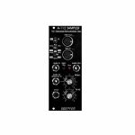
Doepfer A-112v Sampler VC Sampler & Wavetable Oscillator Vintage Edition Module (black) (delay/digital/oscillator/sampling synth module)
Cat: 671610 Rel: 29 Nov 17
Combined module of voltage-controlled 8-bit sampler & wavetable oscillator - vintage edition, 10HP
Notes: Module A-112 is the combination of a voltage controlled 8 Bit Sampler and a wavetable oscillator. On top of it the module is able to generate some special effects. A-112 was designed as an additional sound source with the typical sounds of the early 8 bit samplers and is not comparable with the modern polyphonic MIDI samplers available on the market.
Sampling mode: 8 bit audio resolution, 128kB memory in 2 banks 64kB each (equivalent to 2 seconds of sampling time for each bank with 32 kHz sampling rate), audio input with attenuator, overload display in record mode (gate LED), possibility of MIDI Dump to store sounds in a computer via MIDI, non-volatile memory for the 2 samples in the module, manual tune control for adjustment of sampling rate for record and play, CV input (~ 1V/Oct), both manual tune and CV determine the sampling rate respectively the pitch (pitch range is 5 octaves), gate input (not a trigger: the sample starts at the positive edge of the gate signal and is played as long as gate is high or until the end of the sample is reached), manual Gate button, non-filtered audio output (thus quantizing noise can be used as an element of the sound intentionally).
Wavetable mode: special appearance of the sampling mode when playing a sample, the audio input is now used as a second control voltage input for moving through the sample in 256 byte wide loops (wavetables). The control voltage required to move through all wavetables applied to the input "Wave CV In" is in the range -2.5V (wavetable 1) ... 0V (wavetable 127) ... +2.5V (wavetable 256) when control "Atten." is set fully clockwise. To achieve the typical wavetable oscillator sounds the sampling memory must contain corresponding wavetable data (e.g. loaded via MIDI dump). These data contain a set of wavetables with different harmonic content (e.g. a filter sweep) to get the typical wavetable sound while moving through the tables via CV. But you may also use a "normal" sample and go through the sample with CV to obtain partially amazing sounds never heard before. You may use for example sampled speech and go with CV through the syllables or speech shreds to get really very extreme sounds. An ideal addition for this feature is the Offset/Attenuator module A-183-2 which can be used to adjust the position of the wavetable (Offset) and the modulation depth (Att.). The corresponding jumper of the A-183-2 has to be set to bipolar offset (as the A-112 requires -2.5V...+2.5V to pass through all 256 wavetables). As modulation source an LFO (A-145, A-146, A-147, A-143-3), ADSR (A-140, A-141, A-142, A-143-1/2) or a random voltage (A-118, A-149-1) may be used. Even a ribbon controller (A-198 or R2M), the Theremin module A-178, the Joystick A-174 or the Wheels module A-174-2 are useful to drive through the wavetables.
Effects: Additionally, the module offers - in a way free of charge - some effects like delay, reverse delay, pitch shifting or freeze. But it has to be pointed out that due to the 8 bit audio resolution these effects are not comparable to high quality effect units and should be understand as an extra for nothing. The A-112 is not an effects unit!
The sampling time of the A-112 is about 1...30 seconds corresponding to a sampling frequency range of about 60kHz...2kHz (64kB@60kHz ~ 1 s, 64kB@2kHz ~ 30 s).
Technical note: the module uses a battery for the non-volatile storage of the sampling data. Batteries have a limited lifespan and have to be inspected at least every two years. For details please refer to the FAQ page of our website: Lifespan of rechargeable batteries (used for memory backup).
… Read moreSampling mode: 8 bit audio resolution, 128kB memory in 2 banks 64kB each (equivalent to 2 seconds of sampling time for each bank with 32 kHz sampling rate), audio input with attenuator, overload display in record mode (gate LED), possibility of MIDI Dump to store sounds in a computer via MIDI, non-volatile memory for the 2 samples in the module, manual tune control for adjustment of sampling rate for record and play, CV input (~ 1V/Oct), both manual tune and CV determine the sampling rate respectively the pitch (pitch range is 5 octaves), gate input (not a trigger: the sample starts at the positive edge of the gate signal and is played as long as gate is high or until the end of the sample is reached), manual Gate button, non-filtered audio output (thus quantizing noise can be used as an element of the sound intentionally).
Wavetable mode: special appearance of the sampling mode when playing a sample, the audio input is now used as a second control voltage input for moving through the sample in 256 byte wide loops (wavetables). The control voltage required to move through all wavetables applied to the input "Wave CV In" is in the range -2.5V (wavetable 1) ... 0V (wavetable 127) ... +2.5V (wavetable 256) when control "Atten." is set fully clockwise. To achieve the typical wavetable oscillator sounds the sampling memory must contain corresponding wavetable data (e.g. loaded via MIDI dump). These data contain a set of wavetables with different harmonic content (e.g. a filter sweep) to get the typical wavetable sound while moving through the tables via CV. But you may also use a "normal" sample and go through the sample with CV to obtain partially amazing sounds never heard before. You may use for example sampled speech and go with CV through the syllables or speech shreds to get really very extreme sounds. An ideal addition for this feature is the Offset/Attenuator module A-183-2 which can be used to adjust the position of the wavetable (Offset) and the modulation depth (Att.). The corresponding jumper of the A-183-2 has to be set to bipolar offset (as the A-112 requires -2.5V...+2.5V to pass through all 256 wavetables). As modulation source an LFO (A-145, A-146, A-147, A-143-3), ADSR (A-140, A-141, A-142, A-143-1/2) or a random voltage (A-118, A-149-1) may be used. Even a ribbon controller (A-198 or R2M), the Theremin module A-178, the Joystick A-174 or the Wheels module A-174-2 are useful to drive through the wavetables.
Effects: Additionally, the module offers - in a way free of charge - some effects like delay, reverse delay, pitch shifting or freeze. But it has to be pointed out that due to the 8 bit audio resolution these effects are not comparable to high quality effect units and should be understand as an extra for nothing. The A-112 is not an effects unit!
The sampling time of the A-112 is about 1...30 seconds corresponding to a sampling frequency range of about 60kHz...2kHz (64kB@60kHz ~ 1 s, 64kB@2kHz ~ 30 s).
Technical note: the module uses a battery for the non-volatile storage of the sampling data. Batteries have a limited lifespan and have to be inspected at least every two years. For details please refer to the FAQ page of our website: Lifespan of rechargeable batteries (used for memory backup).
1 in stock $171.13
Click for better price!
or call +44 20 7424 1960
quote 671610
quote 671610
People also bought...
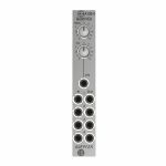
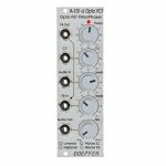
Doepfer A-101-6 6-Stage VC Opto-FET Filter & Phaser Module (silver) (filter/phase shifter/effect synth module)
Cat: 682323 Rel: 26 Mar 18
6-stage VC Opto-FET filter/phaser - 8HP
Notes: A-101-6 is a new filter module that uses so-called opto FET's to control the filter frequency. Opto FET's are very similar to Vactrols, but use light dependent field effect transistors (FET's) instead of light dependent resistors (LDR's). An opto FET is a combination of a light-dependent FET and an LED, both put into a small light-proof case. The advantage, compared to vactrols, is a much faster response of opto FET's compared to LDR's - this allows much faster attack/decay times and even FM effects.
The variable resistors corresponds to the opto FET. The brightness of the Opto FET LED's, and consequently the filter frequency, can be adjusted manually (Frequ. control) and controlled by means of an external control voltage (CV) with attenuator. The LED at the front panel reflects the LED brightness inside the opto FET's.
The type of filter is chosen by jumpers on the PC board (factory setting: low pass). The type of filter determined by the jumpers positions can be marked by means of a water-resistant felt pen at the front panel.
The resonance is controlled by the Feedback control up to self-oscillation. By means of a trimming potentiometer the maximal feedback can be adjusted. High feedback values can be used mainly in the all-pass mode to obtain very extreme self-oscillation sounds. Even an external feedback signal can be used instead of the internal feedback connection (FB In socket). Whenever the filter type is changed by means of the jumpers the trimming potentiometer for the maximal feedback has to be re-adjusted.
The Mix control is used to pan between the original signal (CCW position) and the effect signal (CW position). In filter mode (LP/HP) this control is usually set fully CW. In the all-pass modes one obtains phasing sounds at centre position or "pure" all-pass sound in fully CW position.
… Read moreThe variable resistors corresponds to the opto FET. The brightness of the Opto FET LED's, and consequently the filter frequency, can be adjusted manually (Frequ. control) and controlled by means of an external control voltage (CV) with attenuator. The LED at the front panel reflects the LED brightness inside the opto FET's.
The type of filter is chosen by jumpers on the PC board (factory setting: low pass). The type of filter determined by the jumpers positions can be marked by means of a water-resistant felt pen at the front panel.
The resonance is controlled by the Feedback control up to self-oscillation. By means of a trimming potentiometer the maximal feedback can be adjusted. High feedback values can be used mainly in the all-pass mode to obtain very extreme self-oscillation sounds. Even an external feedback signal can be used instead of the internal feedback connection (FB In socket). Whenever the filter type is changed by means of the jumpers the trimming potentiometer for the maximal feedback has to be re-adjusted.
The Mix control is used to pan between the original signal (CCW position) and the effect signal (CW position). In filter mode (LP/HP) this control is usually set fully CW. In the all-pass modes one obtains phasing sounds at centre position or "pure" all-pass sound in fully CW position.
1 in stock $95.42
People also bought...
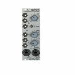
Doepfer A-160-2v Clock/Trigger Divider II Vintage Edition Module (black) (clock modulator/frequency divider synth module)
Cat: 864696 Rel: 14 Mar 22
Module A-160-2 is an enhanced version of the standard clock divider A-160.
Notes: Module A-160-2V is an enhanced version of the standard clock divider A-160. The module is a frequency divider for clock/trigger/gate signals, designed to be a source of lower frequencies, particularly for rhythm uses.
The Clock input will take any digital signal from, eg., an LFO, MIDI sync, or the gate from a MIDI-CV interface. At the outputs, you have access to three sets of seven different sub-divided clock signals, from half the clock frequency down to 1/128. The low/high levels of the output signals are 0V and about +10V.
The A-160-2V also has a reset input. Whenever a reset signal is sensed, all outputs are set to certain levels which depend upon the selected mode.
HP : 4
… Read moreThe Clock input will take any digital signal from, eg., an LFO, MIDI sync, or the gate from a MIDI-CV interface. At the outputs, you have access to three sets of seven different sub-divided clock signals, from half the clock frequency down to 1/128. The low/high levels of the output signals are 0V and about +10V.
The A-160-2V also has a reset input. Whenever a reset signal is sensed, all outputs are set to certain levels which depend upon the selected mode.
HP : 4
5 in stock $107.87
Click for better price!
or call +44 20 7424 1960
quote 864696
quote 864696
People also bought...
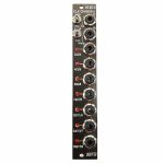
Doepfer A-130-8v Octal Linear VCA Vintage Edition Module (black) (mixer/quad/VCA synth module)
Cat: 852796 Rel: 16 Dec 21
Octal Linear VCA / Voltage Controlled Mixers (Slim Line Series)
Notes: Module A-130-8 contains eight linear voltage controlled amplifiers (VCAs). Each VCA features a control voltage input (CV), a signal input (In) and a signal output (Out). In addition three mixers are included: the socket labelled "1-4" outputs the sum of the VCAs 1-4, the socket labelled "5-8" outputs the sum of the VCAs 5-8, the socket labelled "1-8" outputs the sum of all eight VCAs.
The signal inputs are able to process levels up to 10Vpp without clipping. Each CV input is equipped with a trimming potentiometer that is used to adjust the sensitivity of the CV input in question. In the factory the module is adjusted for the CV range 1...+5V but can be re-adjusted by the user for other control voltage ranges (e.g. 0...+10V).
The amplification range for each single VCA is 0...1. The signals of the sum outputs have a lower amplification to avoid distortion.
The VCAs and mixers are fully DC coupled, i.e. the module can be used for the processing of both audio and control voltage signals. The control voltage and signal inputs can be normalled by means of small solder pads (e.g. 1 > 2 > 3 > 4 and so on, or 1 > 5, 2 > 6, 3 > 7, 4 > 8 for the stereo application mentioned below).
Typical applications:
Any kind of VCA application (e.g. voltage controlled attenuation of audio or control voltage signals)
Two voltage controlled mixers with four channels each
Voltage controlled stereo mixer with four channels each, for this the control voltage inputs have to be correspondingly patched or internally normalled: CV1=CV5 / CV2=CV6 / CV3=CV7 / CV4=CV8
Voltage controlled mixer with eight channels
Add-on for the planned Joystick module A-174-4
Dimensions
6 HP
40 mm deep
Current Draw
50 mA +12V
50 mA -12V
0 mA 5V
… Read moreThe signal inputs are able to process levels up to 10Vpp without clipping. Each CV input is equipped with a trimming potentiometer that is used to adjust the sensitivity of the CV input in question. In the factory the module is adjusted for the CV range 1...+5V but can be re-adjusted by the user for other control voltage ranges (e.g. 0...+10V).
The amplification range for each single VCA is 0...1. The signals of the sum outputs have a lower amplification to avoid distortion.
The VCAs and mixers are fully DC coupled, i.e. the module can be used for the processing of both audio and control voltage signals. The control voltage and signal inputs can be normalled by means of small solder pads (e.g. 1 > 2 > 3 > 4 and so on, or 1 > 5, 2 > 6, 3 > 7, 4 > 8 for the stereo application mentioned below).
Typical applications:
Any kind of VCA application (e.g. voltage controlled attenuation of audio or control voltage signals)
Two voltage controlled mixers with four channels each
Voltage controlled stereo mixer with four channels each, for this the control voltage inputs have to be correspondingly patched or internally normalled: CV1=CV5 / CV2=CV6 / CV3=CV7 / CV4=CV8
Voltage controlled mixer with eight channels
Add-on for the planned Joystick module A-174-4
Dimensions
6 HP
40 mm deep
Current Draw
50 mA +12V
50 mA -12V
0 mA 5V
1 in stock $121.35
Click for better price!
or call +44 20 7424 1960
quote 852796
quote 852796
People also bought...
Doepfer A-126-2exp Voltage Controlled Frequency Shifter II - Expansion Module (silver) (expander synth module)
Cat: 852803 Rel: 04 Feb 22
An expander for the A-126-2 Voltage Controlled Frequency Shifter.
Notes: The Doepfer A-126-2exp is an expander for the A-126-2 Voltage Controlled Frequency Shifter.
It adds two outputs from the Dome filter (+45 and -45 degrees) as well as separate outputs from the ring modulators 1 and 2, and from the internal envelope generator. Furthermore, it offers dedicated outputs for Up and Down Shift, allowing the module to be patched in stereo.
*Note: The expander can only be used in conjunction with the module A-126-2.
HP : 2
… Read moreIt adds two outputs from the Dome filter (+45 and -45 degrees) as well as separate outputs from the ring modulators 1 and 2, and from the internal envelope generator. Furthermore, it offers dedicated outputs for Up and Down Shift, allowing the module to be patched in stereo.
*Note: The expander can only be used in conjunction with the module A-126-2.
HP : 2
1 in stock $52.38
Click for better price!
or call +44 20 7424 1960
quote 852803
quote 852803
People also bought...
Doepfer A-126-2exp Voltage Controlled Frequency Shifter II - Expansion Vintage Edition Module (black) (expander synth module)
Cat: 852807 Rel: 04 Feb 22
An expander for the A-126-2 Voltage Controlled Frequency Shifter.
Notes: The Doepfer A-126-2exp is an expander for the A-126-2 Voltage Controlled Frequency Shifter.
It adds two outputs from the Dome filter (+45 and -45 degrees) as well as separate outputs from the ring modulators 1 and 2, and from the internal envelope generator. Furthermore, it offers dedicated outputs for Up and Down Shift, allowing the module to be patched in stereo.
*Note: The expander can only be used in conjunction with the module A-126-2.
HP : 2
… Read moreIt adds two outputs from the Dome filter (+45 and -45 degrees) as well as separate outputs from the ring modulators 1 and 2, and from the internal envelope generator. Furthermore, it offers dedicated outputs for Up and Down Shift, allowing the module to be patched in stereo.
*Note: The expander can only be used in conjunction with the module A-126-2.
HP : 2
2 in stock $51.85
Click for better price!
or call +44 20 7424 1960
quote 852807
quote 852807
People also bought...
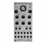
Doepfer A-121s Stereo Multimode Filter Module (silver) (dual/stereo/filter synth module)
Cat: 880248 Rel: 19 Aug 22
Module A-121s is a dual multimode filter which can be used for stereo applications as well as for parallel or serial organized dual mono filters.
Notes: Module A-121s is a dual multimode filter which can be used for stereo applications as well as for parallel or serial organized dual mono filters. The core is a 12dB multimode filter identical to the modules A-121-2 and A-121-3. The selection of the filter type is continuously from lowpass via notch and highpass to bandpass. We attached great importance to the usability of the manual controls and CV inputs for both stereo and dual mono applications. For the filter parameters frequency (F), resonance (Q) and type (T) common controls and CV inputs as well as single controls and CV inputs are available. For the filter frequency in addition a manual control and CV input for the filter spread (frequency difference or delta F) is available.
Controls:
F: master frequency control for both filters (large knob)
Type 1 / Type 2: filter type panning/morphing L-N-H-B
Link to 1: Toggle switch so that Type 1 also controls type of filter 2 (i.e. simultaneous filter type control for both filters)
SFM1 / SFM2: Single Frequency Modulation controls (polarizers), connected to the corresponding sockets SFM1/SFM2 (socket SFM1 is normalled to a fixed positive voltage, SFM2 is normalled to SFM1, that way the controls SFM1/SFM2 work as frequency controls for each filter provided that no modulation signals are patched to the SFM1/SFM2 sockets)
CFM: common frequency control, controls two VC-polarizers which process the signals connected to the two sockets CFM1/CFM2, CFM2 is normalled to CFM1, that way also the same modulation signal (e.g. an envelope generator) can be used for both filters and the level controlled simultaneously by the CFM control
Delta F: controls the difference between the frequencies of the two filters manually (frequency "spread"), at centre position the frequencies are the same
Delta FM: controls the level of the Delta FM signal (socket), which allows to control the spread between the frequencies also by an external control voltage (e.g. by an LFO or ADSR)
Q: controls the resonance of both filters simultaneously
Level 1 / Level 2: attenuators for the two audio inputs
QM/TM1, QM/TM2: attenuators for the modulation inputs QM/TM1 and QM/TM2
Sockets:
In1 / In2: audio inputs (In2 is normalled to In1)
Out1 / Out2: audio outputs
F: common frequency control input for both filters (~ 1V/oct)
Delta FM: Control voltage for frequency spread, processed by the polarizer Delta FM
SFM1 / SFM2: single frequency modulation inputs, processed by the polarizers SFM1 and SFM2, SFM1 is normalled to a fixed positive voltage, SFM2 is normalled to SFM1#
CFM1 / CFM2: common frequency modulation inputs, processed by the two voltage controlled polarizers controlled by CFM knob, CFM2 is normalled to CFM1
QM/TM1, QM/TM2: the addressing of these sockets/attenuators is defined by internal jumpers. QM means Q modulation (i.e. resonance modulation), TM means filter type modulation (QM1 = resonance modulation filter 1, QM2 = resonance modulation filter 2, TM1 = filter type modulation filter 1, TM2 = filter type modulation filter 2), socket QM/TM1 is normalled to a fixed positive voltage, QM/TM2 is normalled to QM/TM1
A 45 degrees triangle next to a socket means that the switching contact of the socket is normalled to a fixed positive voltage (SFM1, QM/TM1).
A vertical triangle indicates the normalling of two sockets (In1>In2, SFM1>SFM2, CFM1>CFM2, QM/TM1>QM/TM2).
If the filters do not behave as expected please pay attention to these peculiarities:
For the controls SFM1, SFM2, CFM, Delta F and Delta FM the centre position is the neutral position as these are polarizers. If the filter behaves unexpected these controls should be set to centre positions for the time being.
For the controls F, Q, Level 1, Level 2, QM/TM1 und QM/TM2 the fully CCW position is the neutral position as these are standard attenuators. If the filter behaves unexpected at least the controls QM/TM1 and QM/TM2 should be set to fully CCW. Via the normalling of the sockets QM/TM1 and QM/TM2 and the associated controls the filter parameters adjusted by the major controls (e.g. Type 1, Type 2 or Q) may be overwritten.
By means of small circles at the bottom right side of the front panel the user can mark the function of the QM/TM inputs. These assignments are possible:
QM/TM1 controls QM1, QM/TM2 controls QM2, the filter types are not controlled by external CVs
QM/TM1 controls TM1, QM/TM2 controls TM2, the resonances are not controlled by external CVs
QM/TM1 controls QM1 and QM2 simultaneously, QM/TM2 controls TM1 and TM2 simultaneously
Depth: 45mm
HP : 12
… Read moreControls:
F: master frequency control for both filters (large knob)
Type 1 / Type 2: filter type panning/morphing L-N-H-B
Link to 1: Toggle switch so that Type 1 also controls type of filter 2 (i.e. simultaneous filter type control for both filters)
SFM1 / SFM2: Single Frequency Modulation controls (polarizers), connected to the corresponding sockets SFM1/SFM2 (socket SFM1 is normalled to a fixed positive voltage, SFM2 is normalled to SFM1, that way the controls SFM1/SFM2 work as frequency controls for each filter provided that no modulation signals are patched to the SFM1/SFM2 sockets)
CFM: common frequency control, controls two VC-polarizers which process the signals connected to the two sockets CFM1/CFM2, CFM2 is normalled to CFM1, that way also the same modulation signal (e.g. an envelope generator) can be used for both filters and the level controlled simultaneously by the CFM control
Delta F: controls the difference between the frequencies of the two filters manually (frequency "spread"), at centre position the frequencies are the same
Delta FM: controls the level of the Delta FM signal (socket), which allows to control the spread between the frequencies also by an external control voltage (e.g. by an LFO or ADSR)
Q: controls the resonance of both filters simultaneously
Level 1 / Level 2: attenuators for the two audio inputs
QM/TM1, QM/TM2: attenuators for the modulation inputs QM/TM1 and QM/TM2
Sockets:
In1 / In2: audio inputs (In2 is normalled to In1)
Out1 / Out2: audio outputs
F: common frequency control input for both filters (~ 1V/oct)
Delta FM: Control voltage for frequency spread, processed by the polarizer Delta FM
SFM1 / SFM2: single frequency modulation inputs, processed by the polarizers SFM1 and SFM2, SFM1 is normalled to a fixed positive voltage, SFM2 is normalled to SFM1#
CFM1 / CFM2: common frequency modulation inputs, processed by the two voltage controlled polarizers controlled by CFM knob, CFM2 is normalled to CFM1
QM/TM1, QM/TM2: the addressing of these sockets/attenuators is defined by internal jumpers. QM means Q modulation (i.e. resonance modulation), TM means filter type modulation (QM1 = resonance modulation filter 1, QM2 = resonance modulation filter 2, TM1 = filter type modulation filter 1, TM2 = filter type modulation filter 2), socket QM/TM1 is normalled to a fixed positive voltage, QM/TM2 is normalled to QM/TM1
A 45 degrees triangle next to a socket means that the switching contact of the socket is normalled to a fixed positive voltage (SFM1, QM/TM1).
A vertical triangle indicates the normalling of two sockets (In1>In2, SFM1>SFM2, CFM1>CFM2, QM/TM1>QM/TM2).
If the filters do not behave as expected please pay attention to these peculiarities:
For the controls SFM1, SFM2, CFM, Delta F and Delta FM the centre position is the neutral position as these are polarizers. If the filter behaves unexpected these controls should be set to centre positions for the time being.
For the controls F, Q, Level 1, Level 2, QM/TM1 und QM/TM2 the fully CCW position is the neutral position as these are standard attenuators. If the filter behaves unexpected at least the controls QM/TM1 and QM/TM2 should be set to fully CCW. Via the normalling of the sockets QM/TM1 and QM/TM2 and the associated controls the filter parameters adjusted by the major controls (e.g. Type 1, Type 2 or Q) may be overwritten.
By means of small circles at the bottom right side of the front panel the user can mark the function of the QM/TM inputs. These assignments are possible:
QM/TM1 controls QM1, QM/TM2 controls QM2, the filter types are not controlled by external CVs
QM/TM1 controls TM1, QM/TM2 controls TM2, the resonances are not controlled by external CVs
QM/TM1 controls QM1 and QM2 simultaneously, QM/TM2 controls TM1 and TM2 simultaneously
Depth: 45mm
HP : 12
2 in stock $234.41
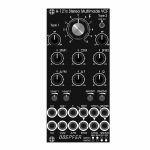
People also bought...
Doepfer A-121sV Stereo Multimode Filter Vintage Edition Module (black) (dual/stereo/filter synth module)
Cat: 880251 Rel: 18 Aug 22
Module A-121s is a dual multimode filter which can be used for stereo applications as well as for parallel or serial organized dual mono filters.
Notes: Module A-121s is a dual multimode filter which can be used for stereo applications as well as for parallel or serial organized dual mono filters. The core is a 12dB multimode filter identical to the modules A-121-2 and A-121-3. The selection of the filter type is continuously from lowpass via notch and highpass to bandpass. We attached great importance to the usability of the manual controls and CV inputs for both stereo and dual mono applications. For the filter parameters frequency (F), resonance (Q) and type (T) common controls and CV inputs as well as single controls and CV inputs are available. For the filter frequency in addition a manual control and CV input for the filter spread (frequency difference or delta F) is available.
Controls:
F: master frequency control for both filters (large knob)
Type 1 / Type 2: filter type panning/morphing L-N-H-B
Link to 1: Toggle switch so that Type 1 also controls type of filter 2 (i.e. simultaneous filter type control for both filters)
SFM1 / SFM2: Single Frequency Modulation controls (polarizers), connected to the corresponding sockets SFM1/SFM2 (socket SFM1 is normalled to a fixed positive voltage, SFM2 is normalled to SFM1, that way the controls SFM1/SFM2 work as frequency controls for each filter provided that no modulation signals are patched to the SFM1/SFM2 sockets)
CFM: common frequency control, controls two VC-polarizers which process the signals connected to the two sockets CFM1/CFM2, CFM2 is normalled to CFM1, that way also the same modulation signal (e.g. an envelope generator) can be used for both filters and the level controlled simultaneously by the CFM control
Delta F: controls the difference between the frequencies of the two filters manually (frequency "spread"), at centre position the frequencies are the same
Delta FM: controls the level of the Delta FM signal (socket), which allows to control the spread between the frequencies also by an external control voltage (e.g. by an LFO or ADSR)
Q: controls the resonance of both filters simultaneously
Level 1 / Level 2: attenuators for the two audio inputs
QM/TM1, QM/TM2: attenuators for the modulation inputs QM/TM1 and QM/TM2
Sockets:
In1 / In2: audio inputs (In2 is normalled to In1)
Out1 / Out2: audio outputs
F: common frequency control input for both filters (~ 1V/oct)
Delta FM: Control voltage for frequency spread, processed by the polarizer Delta FM
SFM1 / SFM2: single frequency modulation inputs, processed by the polarizers SFM1 and SFM2, SFM1 is normalled to a fixed positive voltage, SFM2 is normalled to SFM1#
CFM1 / CFM2: common frequency modulation inputs, processed by the two voltage controlled polarizers controlled by CFM knob, CFM2 is normalled to CFM1
QM/TM1, QM/TM2: the addressing of these sockets/attenuators is defined by internal jumpers. QM means Q modulation (i.e. resonance modulation), TM means filter type modulation (QM1 = resonance modulation filter 1, QM2 = resonance modulation filter 2, TM1 = filter type modulation filter 1, TM2 = filter type modulation filter 2), socket QM/TM1 is normalled to a fixed positive voltage, QM/TM2 is normalled to QM/TM1
A 45 degrees triangle next to a socket means that the switching contact of the socket is normalled to a fixed positive voltage (SFM1, QM/TM1).
A vertical triangle indicates the normalling of two sockets (In1>In2, SFM1>SFM2, CFM1>CFM2, QM/TM1>QM/TM2).
If the filters do not behave as expected please pay attention to these peculiarities:
For the controls SFM1, SFM2, CFM, Delta F and Delta FM the centre position is the neutral position as these are polarizers. If the filter behaves unexpected these controls should be set to centre positions for the time being.
For the controls F, Q, Level 1, Level 2, QM/TM1 und QM/TM2 the fully CCW position is the neutral position as these are standard attenuators. If the filter behaves unexpected at least the controls QM/TM1 and QM/TM2 should be set to fully CCW. Via the normalling of the sockets QM/TM1 and QM/TM2 and the associated controls the filter parameters adjusted by the major controls (e.g. Type 1, Type 2 or Q) may be overwritten.
By means of small circles at the bottom right side of the front panel the user can mark the function of the QM/TM inputs. These assignments are possible:
QM/TM1 controls QM1, QM/TM2 controls QM2, the filter types are not controlled by external CVs
QM/TM1 controls TM1, QM/TM2 controls TM2, the resonances are not controlled by external CVs
QM/TM1 controls QM1 and QM2 simultaneously, QM/TM2 controls TM1 and TM2 simultaneously
… Read moreControls:
F: master frequency control for both filters (large knob)
Type 1 / Type 2: filter type panning/morphing L-N-H-B
Link to 1: Toggle switch so that Type 1 also controls type of filter 2 (i.e. simultaneous filter type control for both filters)
SFM1 / SFM2: Single Frequency Modulation controls (polarizers), connected to the corresponding sockets SFM1/SFM2 (socket SFM1 is normalled to a fixed positive voltage, SFM2 is normalled to SFM1, that way the controls SFM1/SFM2 work as frequency controls for each filter provided that no modulation signals are patched to the SFM1/SFM2 sockets)
CFM: common frequency control, controls two VC-polarizers which process the signals connected to the two sockets CFM1/CFM2, CFM2 is normalled to CFM1, that way also the same modulation signal (e.g. an envelope generator) can be used for both filters and the level controlled simultaneously by the CFM control
Delta F: controls the difference between the frequencies of the two filters manually (frequency "spread"), at centre position the frequencies are the same
Delta FM: controls the level of the Delta FM signal (socket), which allows to control the spread between the frequencies also by an external control voltage (e.g. by an LFO or ADSR)
Q: controls the resonance of both filters simultaneously
Level 1 / Level 2: attenuators for the two audio inputs
QM/TM1, QM/TM2: attenuators for the modulation inputs QM/TM1 and QM/TM2
Sockets:
In1 / In2: audio inputs (In2 is normalled to In1)
Out1 / Out2: audio outputs
F: common frequency control input for both filters (~ 1V/oct)
Delta FM: Control voltage for frequency spread, processed by the polarizer Delta FM
SFM1 / SFM2: single frequency modulation inputs, processed by the polarizers SFM1 and SFM2, SFM1 is normalled to a fixed positive voltage, SFM2 is normalled to SFM1#
CFM1 / CFM2: common frequency modulation inputs, processed by the two voltage controlled polarizers controlled by CFM knob, CFM2 is normalled to CFM1
QM/TM1, QM/TM2: the addressing of these sockets/attenuators is defined by internal jumpers. QM means Q modulation (i.e. resonance modulation), TM means filter type modulation (QM1 = resonance modulation filter 1, QM2 = resonance modulation filter 2, TM1 = filter type modulation filter 1, TM2 = filter type modulation filter 2), socket QM/TM1 is normalled to a fixed positive voltage, QM/TM2 is normalled to QM/TM1
A 45 degrees triangle next to a socket means that the switching contact of the socket is normalled to a fixed positive voltage (SFM1, QM/TM1).
A vertical triangle indicates the normalling of two sockets (In1>In2, SFM1>SFM2, CFM1>CFM2, QM/TM1>QM/TM2).
If the filters do not behave as expected please pay attention to these peculiarities:
For the controls SFM1, SFM2, CFM, Delta F and Delta FM the centre position is the neutral position as these are polarizers. If the filter behaves unexpected these controls should be set to centre positions for the time being.
For the controls F, Q, Level 1, Level 2, QM/TM1 und QM/TM2 the fully CCW position is the neutral position as these are standard attenuators. If the filter behaves unexpected at least the controls QM/TM1 and QM/TM2 should be set to fully CCW. Via the normalling of the sockets QM/TM1 and QM/TM2 and the associated controls the filter parameters adjusted by the major controls (e.g. Type 1, Type 2 or Q) may be overwritten.
By means of small circles at the bottom right side of the front panel the user can mark the function of the QM/TM inputs. These assignments are possible:
QM/TM1 controls QM1, QM/TM2 controls QM2, the filter types are not controlled by external CVs
QM/TM1 controls TM1, QM/TM2 controls TM2, the resonances are not controlled by external CVs
QM/TM1 controls QM1 and QM2 simultaneously, QM/TM2 controls TM1 and TM2 simultaneously
1 in stock $241.67
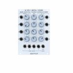
People also bought...
Doepfer A-135-1 QVCA/VCMIX Quad Linear VCA & Voltage Controlled Mixer Module (mixer/quad/VCA synth module)
Cat: 738613 Rel: 09 Jul 19
Quad voltage-controlled mixer with 4 individual VCA's - 18HP
Notes: Module A-135-1 is a quad voltage controlled mixer. It is made of 4 independent linear VCA's. The VCA outputs are mixed to a common output. For each VCA the following inputs and controls are available: audio input with attenuator, control voltage input with attenuator, gain (pre-amplification). The VCA's are realized with high-quality CEM VCA's (CEM3381 for version 1 and SSM2164 for version 2).
Applications: voltage controlled mixing of up to 4 audio signals with separate control voltages (e.g. delivered by LFO's, ADSR's, Random, Shepard generator, MIDI-to-CV interface or other control voltage sources). In connection with the Morphing-Controller A-144 the soft fade-over of 4 audio signals with only one control voltage is possible.
Inputs: 4 x Signal in, 4 x CV In
Output: Signal Out, Version 2 in addition: 4 x Single Out
Controls: 4 x Signal In Attenuator, 4 x CV Attenuator, 4 x Initial Gain
… Read moreApplications: voltage controlled mixing of up to 4 audio signals with separate control voltages (e.g. delivered by LFO's, ADSR's, Random, Shepard generator, MIDI-to-CV interface or other control voltage sources). In connection with the Morphing-Controller A-144 the soft fade-over of 4 audio signals with only one control voltage is possible.
Inputs: 4 x Signal in, 4 x CV In
Output: Signal Out, Version 2 in addition: 4 x Single Out
Controls: 4 x Signal In Attenuator, 4 x CV Attenuator, 4 x Initial Gain
1 in stock $125.39
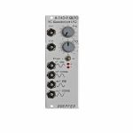
People also bought...
Doepfer A-143-9 QLFO Voltage Controlled Quadrature LFO & VCO Module (oscillator/LFO synth module)
Cat: 738640 Rel: 09 Jul 19
Voltage controlled sine-LFO with four separate, phase shifted outputs - 8HP
Notes: Module A-143-9 is a derivative of our planned thru-zero quadrature VCO. It is a voltage controlled sine LFO with 4 outputs. The phase shift between the outputs is 90 degrees. The sine shifted by 90 degrees is also called cosine, the sine shifted by 180 degrees is nothing but the inverted sine, and the sine by 90 degrees is nothing but the inverted cosine.
The frequency range is from some minutes to frequencies beyond audio with three ranges selected by a toggle switch:
- Switch position H: about 30 Hz ... 3.5 kHz with the manual frequency control ("Frq."), beyond 20 kHz with additional external CV
- Switch position M: about 1 Hz ... 150 Hz with the manual frequency control ("Frq.")
- Switch position L: about 0,1 Hz ... 10 Hz with the manual frequency control ("Frq."), down to several minutes with additional external CV
Two exponential frequency control inputs are available: CV1 without attenuator and CV2 with polarizer. Consequently the module can be used even as an experimental sine VCO but does not feature an exact 1V/oct CV input! The precision CV input will be left to the thru-zero quadrature VCO.
Two LEDs display the positive and negative share of the sine output.
The core of the module is a so-called quadrature circuit that generates a sine a cosine signal with very low distortion. The quality of the sine/cosine signals are much better than those generated by a waveform converter with a sawtooth or triangle signal as starting point.
The output levels are about 5 Vss (+/-2.5V) but can be adjusted internally by a trimming potentiometer (P5 "Shape").
Typical applications:
- External sine/cosine oscillator for the frequency shifter A-126
- Modulations with pure sine/cosine waveforms
- Quadrature/barberpole effects (e.g. with the voltage controlled mixer A-135)
- Experimental sine/cosine VCO (e.g. for FM sounds)
Many users suggested to add a common output level control, i.e. four VCAs with one common control (manual + CV without attenuator + CV with polarizer) for the output levels. This is why we also designed the Quad VCA module A-132-2 with the possibility of an internal default connection to the four outputs of the A-143-9 (no soldering required, short 10 pin flat cable with removable connectors on both ends).
The A-143-9 is also a meaningful addition for the Frequency Shifter module A-126. It enables frequency shifting even below 50 Hz generating e.g. these mellow beat sounds with a few Hz frequency shifting only. The following document describes how to connect the A-126 and the A-143-9: A126_A143_connection.pdf.
The thru zero version of the A-143-9 with temperature compensation is the module A-110-4.
… Read moreThe frequency range is from some minutes to frequencies beyond audio with three ranges selected by a toggle switch:
- Switch position H: about 30 Hz ... 3.5 kHz with the manual frequency control ("Frq."), beyond 20 kHz with additional external CV
- Switch position M: about 1 Hz ... 150 Hz with the manual frequency control ("Frq.")
- Switch position L: about 0,1 Hz ... 10 Hz with the manual frequency control ("Frq."), down to several minutes with additional external CV
Two exponential frequency control inputs are available: CV1 without attenuator and CV2 with polarizer. Consequently the module can be used even as an experimental sine VCO but does not feature an exact 1V/oct CV input! The precision CV input will be left to the thru-zero quadrature VCO.
Two LEDs display the positive and negative share of the sine output.
The core of the module is a so-called quadrature circuit that generates a sine a cosine signal with very low distortion. The quality of the sine/cosine signals are much better than those generated by a waveform converter with a sawtooth or triangle signal as starting point.
The output levels are about 5 Vss (+/-2.5V) but can be adjusted internally by a trimming potentiometer (P5 "Shape").
Typical applications:
- External sine/cosine oscillator for the frequency shifter A-126
- Modulations with pure sine/cosine waveforms
- Quadrature/barberpole effects (e.g. with the voltage controlled mixer A-135)
- Experimental sine/cosine VCO (e.g. for FM sounds)
Many users suggested to add a common output level control, i.e. four VCAs with one common control (manual + CV without attenuator + CV with polarizer) for the output levels. This is why we also designed the Quad VCA module A-132-2 with the possibility of an internal default connection to the four outputs of the A-143-9 (no soldering required, short 10 pin flat cable with removable connectors on both ends).
The A-143-9 is also a meaningful addition for the Frequency Shifter module A-126. It enables frequency shifting even below 50 Hz generating e.g. these mellow beat sounds with a few Hz frequency shifting only. The following document describes how to connect the A-126 and the A-143-9: A126_A143_connection.pdf.
The thru zero version of the A-143-9 with temperature compensation is the module A-110-4.
1 in stock $78.73
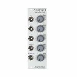
People also bought...
Doepfer A-103 VCF6 18dB Low Pass Filter Module (filter synth module)
Cat: 692504 Rel: 18 Jun 18
18dB low pass filter based on a modified Moog cascade - 8HP
Notes: Module A-103 is a voltage controlled low pass filter with 18dB/octave slope. The circuit is based on a modified transistor ladder (Moog ladder) and is a reproduction of the legendary TB303 filter.
As for the rest the A-103 is identical to the A-120 Moog low pass filter (same controls, inputs/outputs) only the filter sound is different.
… Read moreAs for the rest the A-103 is identical to the A-120 Moog low pass filter (same controls, inputs/outputs) only the filter sound is different.
1 in stock $89.20
Click for better price!
or call +44 20 7424 1960
quote 692504
quote 692504
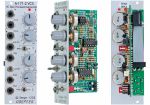
People also bought...
Doepfer A-171-2 Voltage Controlled Slew Processor & Generator Module (silver) (envelope generator/function generator/LFO/oscillator/slew limiter synth module)
Cat: 577809 Rel: 23 Oct 19
Slew processor/generator - 8HP
Notes: Module A-171-2 is a voltage controlled slew limiter with a lot of additional features beyond a simple slew limiter. It's mostly a licensed copy of Ken Stones VCS which is in turn based on the Serge VCS.
Typical applications:
- VC Slew Limiter / VC Portamento / VC Low Pass Gate:
Cycle switch = off, no trigger signal applied to Trig socket: Voltage controlled Slew limiter or portamento generator: the signal applied to the signal input is "slewed". The slew up and down times are controlled manually by means of the Up and Down controls, the effect of the CV Up and CV Down control voltages are controlled by the CV Up and CV Down controls, in exponential mode these controls also affect the slew shape (see symbols at the CCW and CW positions of the controls).
If an audio signal is applied an short slew rates are chosen the module works as a simple VCF/VCA combo.
- A/D Envelope Generator / Pulse Delay / Subharmonic Generator:
Cycle switch = off, trigger signal applied to Trig socket, no input signal: Simple Attack/Decay envelope Generator, the rise and fall times are controlled like the slew up/down times above, including the shape of the falling/rising slope of the envelope, the exp. CV input can be used to change both attack and decay simultaneously.
At the End output a pulse appears as the end of the envelope is reached (less than about 20mV), this can be used as a pulse delay.
If a series of triggers are applied to the VCS faster than the total rise and fall times, the module will divide the incoming signal by a whole number. In the audio range the output will be the sub-harmonic series.
- VCLFO / VCO:
Cycle switch = on, no trigger signal applied to Trig socket, no input signal: Voltage controlled LFO/VCO, the rise and fall times of the waveform are controlled like the slew up/down times above, including the shape of the falling/rising slope
the exp. CV input can be used like the CV input of a VCO or VCLFO, the response is exponential but not exactly 1V/oct.
… Read moreTypical applications:
- VC Slew Limiter / VC Portamento / VC Low Pass Gate:
Cycle switch = off, no trigger signal applied to Trig socket: Voltage controlled Slew limiter or portamento generator: the signal applied to the signal input is "slewed". The slew up and down times are controlled manually by means of the Up and Down controls, the effect of the CV Up and CV Down control voltages are controlled by the CV Up and CV Down controls, in exponential mode these controls also affect the slew shape (see symbols at the CCW and CW positions of the controls).
If an audio signal is applied an short slew rates are chosen the module works as a simple VCF/VCA combo.
- A/D Envelope Generator / Pulse Delay / Subharmonic Generator:
Cycle switch = off, trigger signal applied to Trig socket, no input signal: Simple Attack/Decay envelope Generator, the rise and fall times are controlled like the slew up/down times above, including the shape of the falling/rising slope of the envelope, the exp. CV input can be used to change both attack and decay simultaneously.
At the End output a pulse appears as the end of the envelope is reached (less than about 20mV), this can be used as a pulse delay.
If a series of triggers are applied to the VCS faster than the total rise and fall times, the module will divide the incoming signal by a whole number. In the audio range the output will be the sub-harmonic series.
- VCLFO / VCO:
Cycle switch = on, no trigger signal applied to Trig socket, no input signal: Voltage controlled LFO/VCO, the rise and fall times of the waveform are controlled like the slew up/down times above, including the shape of the falling/rising slope
the exp. CV input can be used like the CV input of a VCO or VCLFO, the response is exponential but not exactly 1V/oct.
1 in stock $121.35
Click for better price!
or call +44 20 7424 1960
quote 577809
quote 577809
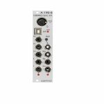
People also bought...
Doepfer A-190-8 USB/MIDI-To-Sync Interface Module (silver) (clock generator/MIDI synth module)
Cat: 755412 Rel: 13 Nov 19
MIDI/USB/CV/Gate interface module - 6HP
Notes: USB/MIDI to clock interface that allows for synchronizing clock-driven modules with the MIDI environment. It processes only the Clock, Start, Stop and Continue MIDI commands. It has several clock divider outputs, each one start, stop and reset outputs for controlling sequencers and also an interesting wait function. Input is either a 5-pin DIN socket or USB.
… Read more 1 in stock $122.39
Click for better price!
or call +44 20 7424 1960
quote 755412
quote 755412
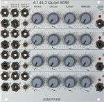
People also bought...
Doepfer A-143-2 Quad ADSR Attack/Decay/Sustain/release Module (silver) (envelope generator/quad/LFO/function generator synth module)
Cat: 577755 Rel: 09 Jul 20
Quad ADSR envelope generator synth module, 26HP wide
Notes: The A-143 series of modules contain multiple modulation sources. Module A-143-2 is a four-fold ADSR type envelope generator. Other modules of this series are the Complex Envelope Generator A-143-1 (Quad AD) and the Quad LFO A-143-3.
The module contains 4 independent ADSR-type envelope generators. Each sub-module has available the controls Attack, Decay, Sustain and Release. The three-position Range switch allows to select the desired time range (low - high - medium). The adjustable envelope time ranges from several minutes to some milliseconds. On top of this each sub-module is equipped with three digital outputs (high/low): "End of Attack (EOA)", "End of Decay (EOD)" and "End of Release (EOR)". As soon as the criterion is valid (e.g. end of decay state) the corresponding digital outputs turns to "high". These outputs can be used e.g. to daisy-chain several ADSR sub-modules. For this the digital output in question (EOA, EOD or EOR) has to be connected to the Gate input of the following ADSR. Even automatically running envelopes (pseudo LFOs) or so-called "quadrature envelopes" with cyclical modulations of several ring-shaped, daisy-chained ADSRs are possible. To obtain a pseudo LFO simply the EOD or EOR output has to be connected to the Gate input of the same ADSR.
In addition to the obligatory Gate (G) input for envelope generators each sub-module has available a Retrigger (Rt) input. The retrigger turns the direction to "upward" if the envelope has already reached the decay state while the retrigger pulse occurs. If the envelope is still in the attack phase the retrigger input has no meaning. This a different behaviour from A-140 and A-141!
The Gate inputs of the units 2, 3 and 4 are normalled to the Gate input of unit 1, i.e. Gate input 1 is connected to the switching contacts of the Gate input sockets 2, 3 and 4. Thus one Gate signal applied to Gate input 1 can be used to trigger all four sub-modules simultaneously.
The envelope outputs are displayed with LEDs.
The maximal envelope voltage (Attack/Decay reversal point) is about +8V.
If voltage control of all parameters is required module A-141 is available.
… Read moreThe module contains 4 independent ADSR-type envelope generators. Each sub-module has available the controls Attack, Decay, Sustain and Release. The three-position Range switch allows to select the desired time range (low - high - medium). The adjustable envelope time ranges from several minutes to some milliseconds. On top of this each sub-module is equipped with three digital outputs (high/low): "End of Attack (EOA)", "End of Decay (EOD)" and "End of Release (EOR)". As soon as the criterion is valid (e.g. end of decay state) the corresponding digital outputs turns to "high". These outputs can be used e.g. to daisy-chain several ADSR sub-modules. For this the digital output in question (EOA, EOD or EOR) has to be connected to the Gate input of the following ADSR. Even automatically running envelopes (pseudo LFOs) or so-called "quadrature envelopes" with cyclical modulations of several ring-shaped, daisy-chained ADSRs are possible. To obtain a pseudo LFO simply the EOD or EOR output has to be connected to the Gate input of the same ADSR.
In addition to the obligatory Gate (G) input for envelope generators each sub-module has available a Retrigger (Rt) input. The retrigger turns the direction to "upward" if the envelope has already reached the decay state while the retrigger pulse occurs. If the envelope is still in the attack phase the retrigger input has no meaning. This a different behaviour from A-140 and A-141!
The Gate inputs of the units 2, 3 and 4 are normalled to the Gate input of unit 1, i.e. Gate input 1 is connected to the switching contacts of the Gate input sockets 2, 3 and 4. Thus one Gate signal applied to Gate input 1 can be used to trigger all four sub-modules simultaneously.
The envelope outputs are displayed with LEDs.
The maximal envelope voltage (Attack/Decay reversal point) is about +8V.
If voltage control of all parameters is required module A-141 is available.
1 in stock $187.89
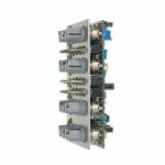
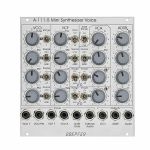
People also bought...
Doepfer A-111-5 Mini Synthesiser Voice Module (silver) (envelope generator/filter/LFO/oscillator/VCA/synth voice synth module)
Cat: 785445 Rel: 10 Sep 20
A complete monophonic synthesiser module (modular version of Dark Energy).
Notes: A fully modular, Eurorack-format version of the excellent Dark Energy synth, the A-111-5 offers VCO, VCF, LFOs, VCA and envelope generator in a compact format. Brilliant value for a starter system.
Supplier's Notes:
Module A-111-5 is a complete monophonic synthesizer module that includes these components (modular version of Dark Energy):
VCO
Manual tune control (with an internal jumper the range can be set to ~ +/-1 half an octave or ~ +/-2.5 octaves)
Range switch -1 / 0 / +1 octave
Frequency range about 10Hz ... 12kHz - FM (frequency modulation) control with modulation source switch (LFO1 / off / ADSR)
Manual pulsewidth control for rectangle waveform
PWM control with modulation source switch (LFO2 / off / ADSR)
Waveform switch (sawtooth / off / triangle)
The sum of the waveform chosen by this switch and the rectangle is fed into the VCF (to turn the rectangle off the PW control has to be set fully CCW)
External CV input for VCO frequency (1V/octave)
External CV input for external PWM of the rectangle - internal CV input for frequency (1V/octave) connected to the A-100 bus via jumper, the jumper can be used to interrupt this internal connection if not wanted
VCF
24 dB low pass
~ 12 octaves frequency range
Manual frequency control
Tracking switch half - off - full (internally connected to the external frequency CV input of the VCO, i.e. the VCF tracks to the VCO if the switch is set to "half" or "full" position)
XM: exponential FM (frequency modulation) control with modulation source switch (LFO2 / off / ADSR)
LM: linear FM (frequency modulation) control to modulate the VCF by the triangle of the VCO in a linear (!) manner
Manual resonance control (up to self oscillation)
External audio input (this signal is added to the VCO signal)
External CV input for filter frequency - 1V/octave tracking for usage of the VCF as a sine wave oscillator (not as precise as the VCO but much better than most of the other filters)
VCA
Manual amplitude control
AM (amplitude modulation) control with modulation source switch (LFO1 / off / ADSR)
External CV input for VCA amplitude - special control scale: exponential scale in the range from about -20dB to -80/90dB, linear scale from about -20dB to 0dB (Remark: this special control scale results in a loudness behaviour that is a bit different from pure linear or exponential VCA)
LFO1 and LFO2
Manual frequency control
Waveform switch (triangle / off / rectangle)
Range switch (low, audio, medium) - LED display (dual green/red color for positive/negative share of the signal)
The inverted LFO1 signal is available as an additional socket (to use the LFO1 signal for external modules)
An internal jumper can be used to select between the LFO1 signal or the inverted LFO1 signal
ADSR
Manual controls for Attack, Decay, Sustain, Release
Range switch (long, short, medium) - blue LED display
ADSR signal is available as an additional socket (to use the ADSR signal for external modules)
Gate input connected to the A-100 bus via jumper, the jumper can be used to interrupt this internal connection if not wanted
Remarks:
As the LFO frequencies can go up to moderate audio range (~ 5kHz) even audio FM effects of VCO (pitch and pulsewidth), VCF and ADSR are possible.
If the VCO is turned off (waveform switch = center position, pulsewidth control = fully CCW) and the VCF resonance is set to maximum the module can be used as a sine oscillator. The sine can be modulated in a linear manner from the triangle wave of the VCO and by LFO2 in an exponential manner at the same time !
From the factory the socket labelled "LFO1" outputs the inverted LFO1 signal. But as the module has several internal pin headers available even another signal may appear at this socket by changing the internal module patch. These six pin headers are available: LFO1 output, LFO2 output, ADSR output, inverter input, inverter output, output socket. The internal default patch is LFO1 -> inverter input, inverter output -> output socket (i.e. socket = inverted LFO1). But even another signal can be patched to this socket (e.g. inverted ADSR, non-inverted LFO1, inverted or non-inverted LFO2). It is also possible to add a blind panel next to the A-111-5 with a couple of sockets that are connected to the corresponding pins of the A-111-5 pc board. The in- and outputs of the VCO, VCF and VCA are not available as pin headers because the VCO, VCF and VCA are internally connected in the circuit which is used in this module.
… Read moreSupplier's Notes:
Module A-111-5 is a complete monophonic synthesizer module that includes these components (modular version of Dark Energy):
VCO
Manual tune control (with an internal jumper the range can be set to ~ +/-1 half an octave or ~ +/-2.5 octaves)
Range switch -1 / 0 / +1 octave
Frequency range about 10Hz ... 12kHz - FM (frequency modulation) control with modulation source switch (LFO1 / off / ADSR)
Manual pulsewidth control for rectangle waveform
PWM control with modulation source switch (LFO2 / off / ADSR)
Waveform switch (sawtooth / off / triangle)
The sum of the waveform chosen by this switch and the rectangle is fed into the VCF (to turn the rectangle off the PW control has to be set fully CCW)
External CV input for VCO frequency (1V/octave)
External CV input for external PWM of the rectangle - internal CV input for frequency (1V/octave) connected to the A-100 bus via jumper, the jumper can be used to interrupt this internal connection if not wanted
VCF
24 dB low pass
~ 12 octaves frequency range
Manual frequency control
Tracking switch half - off - full (internally connected to the external frequency CV input of the VCO, i.e. the VCF tracks to the VCO if the switch is set to "half" or "full" position)
XM: exponential FM (frequency modulation) control with modulation source switch (LFO2 / off / ADSR)
LM: linear FM (frequency modulation) control to modulate the VCF by the triangle of the VCO in a linear (!) manner
Manual resonance control (up to self oscillation)
External audio input (this signal is added to the VCO signal)
External CV input for filter frequency - 1V/octave tracking for usage of the VCF as a sine wave oscillator (not as precise as the VCO but much better than most of the other filters)
VCA
Manual amplitude control
AM (amplitude modulation) control with modulation source switch (LFO1 / off / ADSR)
External CV input for VCA amplitude - special control scale: exponential scale in the range from about -20dB to -80/90dB, linear scale from about -20dB to 0dB (Remark: this special control scale results in a loudness behaviour that is a bit different from pure linear or exponential VCA)
LFO1 and LFO2
Manual frequency control
Waveform switch (triangle / off / rectangle)
Range switch (low, audio, medium) - LED display (dual green/red color for positive/negative share of the signal)
The inverted LFO1 signal is available as an additional socket (to use the LFO1 signal for external modules)
An internal jumper can be used to select between the LFO1 signal or the inverted LFO1 signal
ADSR
Manual controls for Attack, Decay, Sustain, Release
Range switch (long, short, medium) - blue LED display
ADSR signal is available as an additional socket (to use the ADSR signal for external modules)
Gate input connected to the A-100 bus via jumper, the jumper can be used to interrupt this internal connection if not wanted
Remarks:
As the LFO frequencies can go up to moderate audio range (~ 5kHz) even audio FM effects of VCO (pitch and pulsewidth), VCF and ADSR are possible.
If the VCO is turned off (waveform switch = center position, pulsewidth control = fully CCW) and the VCF resonance is set to maximum the module can be used as a sine oscillator. The sine can be modulated in a linear manner from the triangle wave of the VCO and by LFO2 in an exponential manner at the same time !
From the factory the socket labelled "LFO1" outputs the inverted LFO1 signal. But as the module has several internal pin headers available even another signal may appear at this socket by changing the internal module patch. These six pin headers are available: LFO1 output, LFO2 output, ADSR output, inverter input, inverter output, output socket. The internal default patch is LFO1 -> inverter input, inverter output -> output socket (i.e. socket = inverted LFO1). But even another signal can be patched to this socket (e.g. inverted ADSR, non-inverted LFO1, inverted or non-inverted LFO2). It is also possible to add a blind panel next to the A-111-5 with a couple of sockets that are connected to the corresponding pins of the A-111-5 pc board. The in- and outputs of the VCO, VCF and VCA are not available as pin headers because the VCO, VCF and VCA are internally connected in the circuit which is used in this module.
1 in stock $277.98
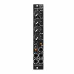
People also bought...
Doepfer A-118-2V Noise/Random/Sample & Hold Vintage Edition Module (black) (noise/random/sample & hold synth module)
Cat: 790467 Rel: 10 Nov 20
Signal generator module
Notes: Module A-118-2 generates the signals white noise, colored noise, continuous random voltage and stepped random voltage.
The noise signal is generated 100% analog by amplification of the noise of a transistor. White and colored noise are usually used as audio sources. The random voltages are normally used as control voltages (e.g. for filter frequency or any other voltage controlled parameter).
The A-118-2 gives you the ability to mix the relative amounts of Red and Blue noise (low/high frequency component) in the colored noise output.
For the continuous random voltage the rate of change (Rate) and amplitude (Level) of the random voltage can be adjusted. The continuous random voltage is used as source for the S&H/T&H unit. The type of operation can be set to S&H (sample and hold) or T&H (track and hold). When T&H is chosen the output signal follows the input signal as long as the Clock input is "high". As soon as the clock signal changes to "low" the last voltage is stored. When S&H is chosen the input signal is sampled at the rising edge of the Clock signal. For the Clock signal a "digital" signal (e.g. Clock, Gate, rectangle output of an LFO) is required. Dual color LEDs are used to indicates the continuous and stepped random voltages.
Controls:
Blue: share of the high frequencies in the the colored noise output
Red: share of the low frequencies in the the colored noise output
Rate: rate of change of the continuous random voltage
Level: amplitude of the continuous random voltage
TH/SH: switches between T&H und S&H
Inputs and outputs:
RND: continuous random voltage output (with LED display)
TH/SH: stepped random voltage output (with LED display)
Clk: Clock input of the S&H/T&H unit
C Noise: colored noise output
W Noise: white noise output
Important notes:
After power on it takes a few minutes until the two noise signals and the random signals are generated. The module is not faulty when after power on the signals do not appear immediately!
The S&H/T&H function is realized by pure analog circuitry (electronic switch followed by a holding capacitor and buffer). Consequently the output voltage drifts a bit in the holding state because the capacitor is discharged by parasitic resistors. The drift depends also upon environmental conditions like humidity or temperature.
The level of the random voltage changes with the settings of the Blue and Red controls. Especially the Red control affects the random voltage level (which is derived by low pass filtering from the colored noise signal) because the Red control changes the share of the low frequencies in the colored noise signal. The effect of the Blue control is much smaller because it changes the share of the high frequencies in the colored noise signal which are filtered out by the low pass of the random circuitry.
Power consumption: 20mA at +12V and 20mA at -12V
Depth: 40mm
HP : 4
… Read moreThe noise signal is generated 100% analog by amplification of the noise of a transistor. White and colored noise are usually used as audio sources. The random voltages are normally used as control voltages (e.g. for filter frequency or any other voltage controlled parameter).
The A-118-2 gives you the ability to mix the relative amounts of Red and Blue noise (low/high frequency component) in the colored noise output.
For the continuous random voltage the rate of change (Rate) and amplitude (Level) of the random voltage can be adjusted. The continuous random voltage is used as source for the S&H/T&H unit. The type of operation can be set to S&H (sample and hold) or T&H (track and hold). When T&H is chosen the output signal follows the input signal as long as the Clock input is "high". As soon as the clock signal changes to "low" the last voltage is stored. When S&H is chosen the input signal is sampled at the rising edge of the Clock signal. For the Clock signal a "digital" signal (e.g. Clock, Gate, rectangle output of an LFO) is required. Dual color LEDs are used to indicates the continuous and stepped random voltages.
Controls:
Blue: share of the high frequencies in the the colored noise output
Red: share of the low frequencies in the the colored noise output
Rate: rate of change of the continuous random voltage
Level: amplitude of the continuous random voltage
TH/SH: switches between T&H und S&H
Inputs and outputs:
RND: continuous random voltage output (with LED display)
TH/SH: stepped random voltage output (with LED display)
Clk: Clock input of the S&H/T&H unit
C Noise: colored noise output
W Noise: white noise output
Important notes:
After power on it takes a few minutes until the two noise signals and the random signals are generated. The module is not faulty when after power on the signals do not appear immediately!
The S&H/T&H function is realized by pure analog circuitry (electronic switch followed by a holding capacitor and buffer). Consequently the output voltage drifts a bit in the holding state because the capacitor is discharged by parasitic resistors. The drift depends also upon environmental conditions like humidity or temperature.
The level of the random voltage changes with the settings of the Blue and Red controls. Especially the Red control affects the random voltage level (which is derived by low pass filtering from the colored noise signal) because the Red control changes the share of the low frequencies in the colored noise signal. The effect of the Blue control is much smaller because it changes the share of the high frequencies in the colored noise signal which are filtered out by the low pass of the random circuitry.
Power consumption: 20mA at +12V and 20mA at -12V
Depth: 40mm
HP : 4
1 in stock $94.39
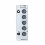
People also bought...
Doepfer A-115 Audio Divider Module (frequency divider synth module)
Cat: 698545 Rel: 15 Aug 18
Fourfold frequency divider for creating up to four sub-octaves - 8HP
Notes: Module A-115 is a four-way frequency divider. The frequency of a signal at the input is halved (half frequency = first sub-octave), quartered (1/4 frequency = second sub-octave), and so on. In this way, the DIVIDER produces four sub-octaves (F/2 down to F/16).
At the output, the A-115 produces a summed mix of the original and the four sub-octaves. There are attenuators to control the amount (i.e. Amplitude) of the original signal and each of the sub-octaves.
Bear in mind that the sub-octaves output by the A-115 are all true square waves. At the output there are always four square waves and the original signal available.
… Read moreAt the output, the A-115 produces a summed mix of the original and the four sub-octaves. There are attenuators to control the amount (i.e. Amplitude) of the original signal and each of the sub-octaves.
Bear in mind that the sub-octaves output by the A-115 are all true square waves. At the output there are always four square waves and the original signal available.
1 in stock $65.33
Click for better price!
or call +44 20 7424 1960
quote 698545
quote 698545
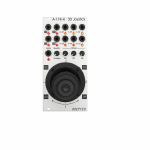
People also bought...
Doepfer A-174-4 3D Joystick Module (silver) (controller/CV modulation/expression module)
Cat: 765892 Rel: 30 Oct 20
Control voltage module - 12HP
Notes: Module A-174-4 modules outputs three control voltages generated by a spring-loaded X/Y cross potentiometer (so-called joy stick) and a Gate signal. The control voltages for X and Y are controlled by the X and Y position of the joystick in the usual way. The third control voltage Z is controlled by the rotation of the spring-loaded joystick knob. The Gate signal is generated by a button at the center/top of the joystick knob.
For each control voltage the non-inverted signal (X, Y, Z) as well as the inverted signal with adjustable offset (-X+XO, -Y+YO, -Z+ZO) are available. The generic joystick control voltages are bipolar, i.e. they range from typ. -5V (lowest position) via 0V (center position) to typ. +5V (highest position). The "Overlap" switches can be used to add a fixed offset voltage of typ. +5V to the non-inverting output in question so that the output voltage range changes to typ. 0...+10V (rather than -5...+5V). That's necessary if e.g. a VCA has to be controlled, which requires a pure positive control voltage range. The switches are named "overlap" because they allow the overlapping of the non-inverting CV output (X, Y, Z) with the inverting output (-X+XO, -Y+YO, -Z+ZO) for crossfading applications. With the overlap switch "on" and appropriate setting of the offset control it's possible to obtain a control voltage range of 0...+10V for the non-inverting output and +10V...0V (i.e. same range but opposite direction) for the inverting output.
The offset voltages which are added to the inverting outputs can be adjusted by means of three small potentiometers. That way different kinds of control voltage ranges are possible, e.g.
-5V ... +5V for the non-inverting output and +5V ... -5V for the inverting output ( Overlap = off, Offset = 0)
0 ... +10V for the non-inverting output and +10V ... 0V for the inverting output ( Overlap = on, Offset = max)
-5V ... +5V for the non-inverting output and +10V ... 0V for the inverting output ( Overlap = off, Offset = max)
0 ... +10V for the non-inverting output and +5V ... -5V for the inverting output ( Overlap = on, Offset = 0)
On top of this the four quadrant voltages Q1, Q2, Q3 and Q4 are available. A quadrant voltage becomes positive when the joystick is positioned in the quadrant in question.
Each CV output is equipped with an LED that displays the present voltage.
Because of the construction height of the joystick (about 7 cm) the module cannot be installed into the cases A-100P6, A-100P9, A-100PMS6, A-100PMS9 and A-100PMS12 during transportation as the depth of the case cover is not sufficient. Into the base cases A-100PB and A-100PMB as well as in all other cases without cover the module can be installed without problems.
HP : 12
… Read moreFor each control voltage the non-inverted signal (X, Y, Z) as well as the inverted signal with adjustable offset (-X+XO, -Y+YO, -Z+ZO) are available. The generic joystick control voltages are bipolar, i.e. they range from typ. -5V (lowest position) via 0V (center position) to typ. +5V (highest position). The "Overlap" switches can be used to add a fixed offset voltage of typ. +5V to the non-inverting output in question so that the output voltage range changes to typ. 0...+10V (rather than -5...+5V). That's necessary if e.g. a VCA has to be controlled, which requires a pure positive control voltage range. The switches are named "overlap" because they allow the overlapping of the non-inverting CV output (X, Y, Z) with the inverting output (-X+XO, -Y+YO, -Z+ZO) for crossfading applications. With the overlap switch "on" and appropriate setting of the offset control it's possible to obtain a control voltage range of 0...+10V for the non-inverting output and +10V...0V (i.e. same range but opposite direction) for the inverting output.
The offset voltages which are added to the inverting outputs can be adjusted by means of three small potentiometers. That way different kinds of control voltage ranges are possible, e.g.
-5V ... +5V for the non-inverting output and +5V ... -5V for the inverting output ( Overlap = off, Offset = 0)
0 ... +10V for the non-inverting output and +10V ... 0V for the inverting output ( Overlap = on, Offset = max)
-5V ... +5V for the non-inverting output and +10V ... 0V for the inverting output ( Overlap = off, Offset = max)
0 ... +10V for the non-inverting output and +5V ... -5V for the inverting output ( Overlap = on, Offset = 0)
On top of this the four quadrant voltages Q1, Q2, Q3 and Q4 are available. A quadrant voltage becomes positive when the joystick is positioned in the quadrant in question.
Each CV output is equipped with an LED that displays the present voltage.
Because of the construction height of the joystick (about 7 cm) the module cannot be installed into the cases A-100P6, A-100P9, A-100PMS6, A-100PMS9 and A-100PMS12 during transportation as the depth of the case cover is not sufficient. Into the base cases A-100PB and A-100PMB as well as in all other cases without cover the module can be installed without problems.
HP : 12
1 in stock $147.96
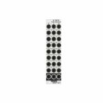
People also bought...
Doepfer A-130-8 Octal Linear VCA/Voltage Controlled Mixers Slim Line Series Module (silver) (mixer/Quad/VCA synth module)
Cat: 765896 Rel: 28 Jul 20
linear VCA module
Notes: Lots of functionality in a compact format thanks to Doepfer's typically smart approach. Eight linear VCAs with three mixers built in for good measure. Can be used for both audio and CV signals. Versatile.
Supplier notes:
Module A-130-8 contains eight linear voltage controlled amplifiers (VCAs). Each VCA features a control voltage input (CV), a signal input (In) and a signal output (Out). In addition three mixers are included: the socket labelled "1-4" outputs the sum of the VCAs 1-4, the socket labelled "5-8" outputs the sum of the VCAs 5-8, the socket labelled "1-8" outputs the sum of all eight VCAs.
The signal inputs are able to process levels up to 10Vpp without clipping. Each CV input is equipped with a trimming potentiometer that is used to adjust the sensitivity of the CV input in question. In the factory the module is adjusted for the CV range 1...+5V but can be re-adjusted by the user for other control voltage ranges (e.g. 0...+10V).
The amplification range for each single VCA is 0...1. The signals of the sum outputs have a lower amplification to avoid distortion.
The VCAs and mixers are fully DC coupled, i.e. the module can be used for the processing of both audio and control voltage signals. The control voltage and signal inputs can be normalled by means of small solder pads (e.g. 1 > 2 > 3 > 4 and so on, or 1 > 5, 2 > 6, 3 > 7, 4 > 8 for the stereo application mentioned below).
Typical applications:
any kind of VCA application (e.g. voltage controlled attenuation of audio or control voltage signals)
two voltage controlled mixers with four channels each
voltage controlled stereo mixer with four channels each, for this the control voltage inputs have to be correspondingly patched or internally normalled: CV1=CV5 /CV 2=CV6 / CV3=CV7 / CV4=CV8
voltage controlled mixer with eight channels
add-on for the planned Joystick module A-174-4
HP : 6
… Read moreSupplier notes:
Module A-130-8 contains eight linear voltage controlled amplifiers (VCAs). Each VCA features a control voltage input (CV), a signal input (In) and a signal output (Out). In addition three mixers are included: the socket labelled "1-4" outputs the sum of the VCAs 1-4, the socket labelled "5-8" outputs the sum of the VCAs 5-8, the socket labelled "1-8" outputs the sum of all eight VCAs.
The signal inputs are able to process levels up to 10Vpp without clipping. Each CV input is equipped with a trimming potentiometer that is used to adjust the sensitivity of the CV input in question. In the factory the module is adjusted for the CV range 1...+5V but can be re-adjusted by the user for other control voltage ranges (e.g. 0...+10V).
The amplification range for each single VCA is 0...1. The signals of the sum outputs have a lower amplification to avoid distortion.
The VCAs and mixers are fully DC coupled, i.e. the module can be used for the processing of both audio and control voltage signals. The control voltage and signal inputs can be normalled by means of small solder pads (e.g. 1 > 2 > 3 > 4 and so on, or 1 > 5, 2 > 6, 3 > 7, 4 > 8 for the stereo application mentioned below).
Typical applications:
any kind of VCA application (e.g. voltage controlled attenuation of audio or control voltage signals)
two voltage controlled mixers with four channels each
voltage controlled stereo mixer with four channels each, for this the control voltage inputs have to be correspondingly patched or internally normalled: CV1=CV5 /CV 2=CV6 / CV3=CV7 / CV4=CV8
voltage controlled mixer with eight channels
add-on for the planned Joystick module A-174-4
HP : 6
1 in stock $97.96
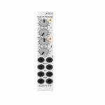
People also bought...
Doepfer A-133-2 Dual Voltage Controlled VCA/Polarizer/Inverter/Ring Modulator Module (silver) (attenuator/dual/stereo/polarizer/ring modulator/VCA synth module)
Cat: 765897 Rel: 28 Jul 20
VCA/polarizer/inverter/ring modulator module
Notes: A-133-2 is the slim version of the A-133 but has some additional features and improvements available compared to the A-133.
Module A-133-2 can be used for a lot of applications: as a simple VCA, or a voltage controlled polarizer/attuverter, or a voltage controlled inverter up to a DC coupled ring modulator. In principle the module contains two special voltage controlled amplifiers (VCAs) that allow both positive and negative amplification.
The overall amplification is definded by the sum of the voltage generated by the Man control, the external control voltage CV and the position of the CV control which works as an attenuator for the external control voltage. Without external CV the amplification is +1 when the Man control is fully CW. In the center position the amplification is zero and fully CCW it's -1 (i.e. the incoming signal is inverted). By means of the external control voltage CV the manually adjusted amplification can be modulated. CV can be both positive or negative (i.e. bipolar) to obtain positive or negative amplification values controlled by the external CV.
In addition the CV signal can be modulated via the modulation control input Mod by means of another control voltage. The Mod socket is normalled to +5V, i.e. a constant positive voltage is used as modulation CV provided that no plug is inserted into the Mod socket.
The current amplification is displayed by a dual color LED (note: it's not a signal display but indicates the amplification, probably yellow = positive amplification, red = negative amplification)
Application examples:
voltage controlled amplifier (VCA) with pure positive overall amplification (Man + CV)
voltage controlled inverter with pure negative overall amplification (Man + CV)
voltage controlled polarizer/attuverter overall amplification changing between positive and negative (Man + CV)
DC coupled ring modulator with offset feature, the "classical" ring modulator corresponds to Man=0 and symmetrical audio signals for In and CV
additional effects by means of the modulation feature of the CV signal (using the Mod input)
… Read moreModule A-133-2 can be used for a lot of applications: as a simple VCA, or a voltage controlled polarizer/attuverter, or a voltage controlled inverter up to a DC coupled ring modulator. In principle the module contains two special voltage controlled amplifiers (VCAs) that allow both positive and negative amplification.
The overall amplification is definded by the sum of the voltage generated by the Man control, the external control voltage CV and the position of the CV control which works as an attenuator for the external control voltage. Without external CV the amplification is +1 when the Man control is fully CW. In the center position the amplification is zero and fully CCW it's -1 (i.e. the incoming signal is inverted). By means of the external control voltage CV the manually adjusted amplification can be modulated. CV can be both positive or negative (i.e. bipolar) to obtain positive or negative amplification values controlled by the external CV.
In addition the CV signal can be modulated via the modulation control input Mod by means of another control voltage. The Mod socket is normalled to +5V, i.e. a constant positive voltage is used as modulation CV provided that no plug is inserted into the Mod socket.
The current amplification is displayed by a dual color LED (note: it's not a signal display but indicates the amplification, probably yellow = positive amplification, red = negative amplification)
Application examples:
voltage controlled amplifier (VCA) with pure positive overall amplification (Man + CV)
voltage controlled inverter with pure negative overall amplification (Man + CV)
voltage controlled polarizer/attuverter overall amplification changing between positive and negative (Man + CV)
DC coupled ring modulator with offset feature, the "classical" ring modulator corresponds to Man=0 and symmetrical audio signals for In and CV
additional effects by means of the modulation feature of the CV signal (using the Mod input)
1 in stock $97.50
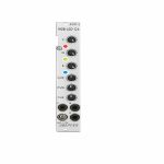
People also bought...
Doepfer A-197-3 RGB LED Stripe Controller Module (silver) (utility synth module)
Cat: 714708 Rel: 25 Mar 19
Controller module for static & dynamic control of RGB LED stripes - 4HP
Notes: Module A-197-3 is a control unit for RGB LED stripes. The LED stripe is glued e.g. to the inner edges of the cases A-100P6/P9/PMS6/PMS9/PMS12 to illuminate the modules and patching statically or dynamically. Especially during live events the dynamic illumination in sync with the sound is an eye-catcher. Each colour (red, green, blue) has available a manual control for the background brightness and a CV input with attenuator that enables the dynamic brightness controlled by other control voltages of the modular system. For example three envelopes can be used which also control the loudness or filtering of sound processing modules. But even other control applications are possible, e.g. LFO, random voltages, clock/gate/trigger signals, sequencer, Midi-to-CV.
… Read more 1 in stock $89.20
Click for better price!
or call +44 20 7424 1960
quote 714708
quote 714708
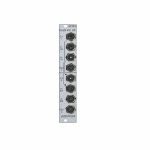
People also bought...
Doepfer A-134-2 Dual Voltage Controlled Crossfader Module (VCA/dual/stereo/panning synth module)
Cat: 716922 Rel: 29 Jan 19
Dual crossfader module for voltage controlled morphing between two audio or CV signals
Notes: Module A-134-2 contains two identical voltage controlled crossfader units.
Each unit has two voltage controlled amplifiers (VCAs) with opposite control behaviour available. The outputs of the two VCAs are mixed together to obtain a common output. The behaviour of the control voltage inputs can be chosen with an internal jumper:
Symmetrical mode: If the corresponding jumper is not set both VCAs of the crossfader have the same 50% amplification with zero CV. If the applied CV becomes positive the amplification of VCA1 decreases and those of VCA2 increases in the same way. A negative CV has the opposite result. The CV voltage range to obtain the maximum/minimum positions of the crossfader is about -2.5....+2.5V. This mode is useful for bidirectional (i.e. positive and negative) control voltages, for example LFO or joy stick (adjusted to 0V CV in centre position).
Asymmetrical mode: If the corresponding jumper is set VCA2 is fully closed and VCA1 has full 100% amplification with zero CV. If the applied CV becomes positive the amplification of VCA1 decreases and those of VCA2 increases in the same way. The CV voltage range to obtain the maximum/minimum positions of the crossfader is about 0...+5V. A negative CV has no function in this mode. This mode is useful for unidirectional (i.e. only positive) control voltages, for example ADSR, ribbon controller or Theremin control voltage.
The CV input of the upper unit (CV1) is normalled to the CV input of the lower unit (CV2). I.e. if no plug is inserted to CV2 the CV input of the upper unit (CV1) also controls the lower unit.
The second signal input of the upper unit (In1B) is normalled to the first signal input of the lower unit (In2A). I.e. if no plug is inserted into In2A the signal In1B is used as the first signal input of the second unit.
As the inputs and outputs are DC coupled the module can be used for both audio and control voltage signal processing.
… Read moreEach unit has two voltage controlled amplifiers (VCAs) with opposite control behaviour available. The outputs of the two VCAs are mixed together to obtain a common output. The behaviour of the control voltage inputs can be chosen with an internal jumper:
Symmetrical mode: If the corresponding jumper is not set both VCAs of the crossfader have the same 50% amplification with zero CV. If the applied CV becomes positive the amplification of VCA1 decreases and those of VCA2 increases in the same way. A negative CV has the opposite result. The CV voltage range to obtain the maximum/minimum positions of the crossfader is about -2.5....+2.5V. This mode is useful for bidirectional (i.e. positive and negative) control voltages, for example LFO or joy stick (adjusted to 0V CV in centre position).
Asymmetrical mode: If the corresponding jumper is set VCA2 is fully closed and VCA1 has full 100% amplification with zero CV. If the applied CV becomes positive the amplification of VCA1 decreases and those of VCA2 increases in the same way. The CV voltage range to obtain the maximum/minimum positions of the crossfader is about 0...+5V. A negative CV has no function in this mode. This mode is useful for unidirectional (i.e. only positive) control voltages, for example ADSR, ribbon controller or Theremin control voltage.
The CV input of the upper unit (CV1) is normalled to the CV input of the lower unit (CV2). I.e. if no plug is inserted to CV2 the CV input of the upper unit (CV1) also controls the lower unit.
The second signal input of the upper unit (In1B) is normalled to the first signal input of the lower unit (In2A). I.e. if no plug is inserted into In2A the signal In1B is used as the first signal input of the second unit.
As the inputs and outputs are DC coupled the module can be used for both audio and control voltage signal processing.
1 in stock $72.60
Click for better price!
or call +44 20 7424 1960
quote 716922
quote 716922
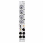
People also bought...
Doepfer A-118-2 Noise/Random/Sample & Hold Slim Line Module (silver) (noise/random/sample & hold module)
Cat: 731938 Rel: 10 Jun 19
Noise, random, sample & hold module - 4HP
Notes: Module A-118-2 is the slim version of module A-118-1 and offers essentially the same features as the A-118-1. But the distances between the controls are smaller and rubberized small-sized knobs are used. In return the front panel has 4 HP only which is half the width of the A-118-1. The module is primarily planned for applications where only limited space is available. The functional difference between A-118-1 and A-118-2 is the additional T&H/S&H unit which is not included in the A-118-1.
The module generates the signals white noise, colored noise, continuous random voltage and stepped random voltage (derived from the continuous random voltage by means of a S&H/T&H unit).
The noise signal is generated 100% analog by amplification of the noise of a transistor. White and colored noise are usually used as audio sources. The random voltages are normally used as control voltages (e.g. for filter frequency or any other voltage controlled parameter).
The A-118-2 gives you the ability to mix the relative amounts of Red (low frequency component) and Blue noise (high frequency component) in the colored noise output.
For the continuous random voltage the rate of change (Rate) and amplitude (Level) of the random voltage can be adjusted. The continuous random voltage is derived from the colored noise signal by low pass filtering. Consequently the settings of the controls for the colored noise (Blue, Red) affect the behavior of the random voltage! A dual color LED (red = positive / yellow = negative output voltage) indicates the continuous random voltage.
The continuous random voltage is used as source for the S&H/T&H unit. The type of operation can be set to S&H (sample and hold) or T&H (track and hold). When T&H is chosen the output signal follows the input signal (= continuous random voltage) as long as the Clock input is "high". As soon as the clock signal changes to "low" the last voltage is stored. When S&H is chosen the input signal (= continuous random voltage) is sampled at the rising edge of the Clock signal.
For the Clock signal a "digital" signal (e.g. Clock, Gate, rectangle output of an LFO) is required. It does not work with slowly changing continuous CV signals. Another dual color LED (red = positive / yellow = negative output voltage) indicates the stepped random voltage.
Controls:
Blue: share of the high frequencies in the the colored noise output
Red: share of the low frequencies in the the colored noise output
Rate: rate of change of the continuous random voltage
Level: amplitude of the continuous random voltage
TH/SH: switches between T&H and S&H
Inputs and outputs:
RND: continuous random voltage output (with LED display)
TH/SH: stepped random voltage output (with LED display)
Clk: Clock input of the S&H/T&H unit
C Noise: colored noise output
W Noise: white noise output
Important notes:
After power on it takes a few minutes until the two noise signals and the random signals are generated. The module is not faulty when after power on the signals do not appear immediately!
The S&H/T&H function is realized by pure analog circuitry (electronic switch followed by a holding capacitor and buffer). Consequently the output voltage drifts a bit in the holding state because the capacitor is discharged by parasitic resistors. The drift depends also upon environmental conditions like humidity or temperature.
Dimensions
4 HP
40 mm deep
Current Draw
20 mA +12V
20 mA -12V
… Read moreThe module generates the signals white noise, colored noise, continuous random voltage and stepped random voltage (derived from the continuous random voltage by means of a S&H/T&H unit).
The noise signal is generated 100% analog by amplification of the noise of a transistor. White and colored noise are usually used as audio sources. The random voltages are normally used as control voltages (e.g. for filter frequency or any other voltage controlled parameter).
The A-118-2 gives you the ability to mix the relative amounts of Red (low frequency component) and Blue noise (high frequency component) in the colored noise output.
For the continuous random voltage the rate of change (Rate) and amplitude (Level) of the random voltage can be adjusted. The continuous random voltage is derived from the colored noise signal by low pass filtering. Consequently the settings of the controls for the colored noise (Blue, Red) affect the behavior of the random voltage! A dual color LED (red = positive / yellow = negative output voltage) indicates the continuous random voltage.
The continuous random voltage is used as source for the S&H/T&H unit. The type of operation can be set to S&H (sample and hold) or T&H (track and hold). When T&H is chosen the output signal follows the input signal (= continuous random voltage) as long as the Clock input is "high". As soon as the clock signal changes to "low" the last voltage is stored. When S&H is chosen the input signal (= continuous random voltage) is sampled at the rising edge of the Clock signal.
For the Clock signal a "digital" signal (e.g. Clock, Gate, rectangle output of an LFO) is required. It does not work with slowly changing continuous CV signals. Another dual color LED (red = positive / yellow = negative output voltage) indicates the stepped random voltage.
Controls:
Blue: share of the high frequencies in the the colored noise output
Red: share of the low frequencies in the the colored noise output
Rate: rate of change of the continuous random voltage
Level: amplitude of the continuous random voltage
TH/SH: switches between T&H and S&H
Inputs and outputs:
RND: continuous random voltage output (with LED display)
TH/SH: stepped random voltage output (with LED display)
Clk: Clock input of the S&H/T&H unit
C Noise: colored noise output
W Noise: white noise output
Important notes:
After power on it takes a few minutes until the two noise signals and the random signals are generated. The module is not faulty when after power on the signals do not appear immediately!
The S&H/T&H function is realized by pure analog circuitry (electronic switch followed by a holding capacitor and buffer). Consequently the output voltage drifts a bit in the holding state because the capacitor is discharged by parasitic resistors. The drift depends also upon environmental conditions like humidity or temperature.
Dimensions
4 HP
40 mm deep
Current Draw
20 mA +12V
20 mA -12V
2 in stock $86.08
Click for better price!
or call +44 20 7424 1960
quote 731938
quote 731938
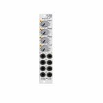
People also bought...
Doepfer A-145-4 LFOs Quad Low Frequency Oscillator Slim Line Module (silver) (LFO/quad synth module)
Cat: 731949 Rel: 10 Jun 19
Quad low frequency oscillator - 4HP
Notes: Module A-145-4 is a simple quad LFO (Low Frequency Oscillator). Not a very "exciting" module, just a bread-and-butter device and a simple demon for work. Virtually in every modular system several LFOs are required for modulation purposes. The module contains four simple LFOs with the waveforms triangle and rectangle. A dual colour LED (red = positive / yellow = negative output voltage) indicates the triangle output of each LFO. The frequency range can be chosen for each LFO individually by means of a jumper between about 50 Hz ... 0.04 Hz (about 20 seconds, jumper removed) and about 2Hz ... 0.002 (about 8 minutes, jumper installed).
The module can be treated as a slimmed version of the quad LFO A-143-3 as it has similar features available. But the distances between the controls are smaller and rubberized small-sized knobs are used. In return the front panel has 4 HP only which is less than one third of the A-143-3. The module is primarily planned for applications where only limited space is available. The functional difference compared to the A-143-3 are the missing sawtooth outputs and frequency range switches.
… Read moreThe module can be treated as a slimmed version of the quad LFO A-143-3 as it has similar features available. But the distances between the controls are smaller and rubberized small-sized knobs are used. In return the front panel has 4 HP only which is less than one third of the A-143-3. The module is primarily planned for applications where only limited space is available. The functional difference compared to the A-143-3 are the missing sawtooth outputs and frequency range switches.
4 in stock $81.43
Click for better price!
or call +44 20 7424 1960
quote 731949
quote 731949
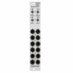
People also bought...
Doepfer A-182-2 Quad Passive Switch Slim Line Series Module (silver) (quad/switch synth module)
Cat: 731951 Rel: 11 Jun 19
Quad passive switch - 4HP
Notes: A-182-2 is a simple passive module that contains four changeover switches, which are used to connect or disconnect the sockets of the corresponding socket triplet:
- In the upper position of the switch the upper socket of the corresponding socket triplet is connected to the centre socket
- In the lower position of the switch the lower socket of the corresponding socket triplet is connected to the centre socket
- In the centre position of the switch the sockets are not connected
Each unit of the module can be used to switch between two signals or to interrupt/connect a signal. In the last case the third socket of the triplet is not used.
The module is fully passive and both audio or control signals can be switched.
… Read more- In the upper position of the switch the upper socket of the corresponding socket triplet is connected to the centre socket
- In the lower position of the switch the lower socket of the corresponding socket triplet is connected to the centre socket
- In the centre position of the switch the sockets are not connected
Each unit of the module can be used to switch between two signals or to interrupt/connect a signal. In the last case the third socket of the triplet is not used.
The module is fully passive and both audio or control signals can be switched.
1 in stock $62.22
Click for better price!
or call +44 20 7424 1960
quote 731951
quote 731951
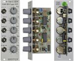
People also bought...
Doepfer A-106-5 SEM 12dB SEM Type VCF Module (silver) (filter synth module)
Cat: 577753 Rel: 06 Jun 19
12dB multi-mode filter - 8HP
Notes: Module A-106-5 is a 12dB multimode filter that is based on the filter circuit of the Oberheim SEM module.
The filter is equipped with a band pass output and a combined low/notch/high pass output. For this output a control knob defines the relation between low and high pass signal. If both signals appear at the same level (i.e. middle position of the Mix knob) one obtains a notch filter. Otherwise the low or high pass signal predominates.
The module does not feature self-oscillation in contrast to most of the other filters of the A-100 system.
The module generates a distorted audio signal if the level control is set to about 50% (i.e. centre position) or more with A-100 standard signals like VCOs.
… Read moreThe filter is equipped with a band pass output and a combined low/notch/high pass output. For this output a control knob defines the relation between low and high pass signal. If both signals appear at the same level (i.e. middle position of the Mix knob) one obtains a notch filter. Otherwise the low or high pass signal predominates.
The module does not feature self-oscillation in contrast to most of the other filters of the A-100 system.
The module generates a distorted audio signal if the level control is set to about 50% (i.e. centre position) or more with A-100 standard signals like VCOs.
1 in stock $80.89
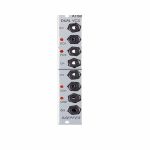
People also bought...
Doepfer A-150 Dual Voltage Controlled Switch Module (silver) (dual/stereo/switch synth module)
Cat: 745778 Rel: 10 Sep 19
Two independent voltage controlled switches in one module - 4HP
Notes: Module A-150-1 (Dual VCS) contains two separate voltage-controlled switches.
Each switch has a control voltage input, a common Out / Input, and two In / Outputs. The switches are bi-directional: they can work in both directions, so can connect one input to either of two outputs, or either of two inputs to one output. Voltages in the range -8V...+8V at the O/I resp. I/O sockets can be processed by the module.
Two LEDs show which in / output is active (i.e. which is connected to the common out / input).
… Read moreEach switch has a control voltage input, a common Out / Input, and two In / Outputs. The switches are bi-directional: they can work in both directions, so can connect one input to either of two outputs, or either of two inputs to one output. Voltages in the range -8V...+8V at the O/I resp. I/O sockets can be processed by the module.
Two LEDs show which in / output is active (i.e. which is connected to the common out / input).
1 in stock $58.08
People also bought...
Doepfer A-160-5v Voltage Controlled Clock Multiplier & Ratcheting Controller Module (vintage edition) (synth module)
Cat: 745789 Rel: 10 Sep 19
Voltage-controlled clock multiplier with CV or manual control - 4HP
Notes: Module A-160-5 is a voltage controlled clock multiplier. The incoming clock signal (socket Clock In) is multiplied by a factor that depends upon the control voltage on socket CV In (0...+5V) and the position of the Mode switch. The multiplied clock signal is available at the socket Clock Out. According to the position of the Mode switch different clock multiplying factors are assigned to the control voltage. With 0V CV no clock output is generated. This state is indicated by "all LEDs off". With increasing CV integer factors (left position of the mode switch), power of two factors (middle position) or a mix of both (right position) are obtained. Nine LEDs are used to show the currently selected multiplying factor. In addition two LEDs are used to display the incoming and outgoing clock signal.
A manual control is used to adjust the clock multiplication factor manually without the need of an external control voltage. The voltage generated by this control ("Manual") is normalled to the CV In socket. As long as no plug is inserted into the CV In socket the clock multiplication factor is adjusted by means of the manual control knob and displayed by the LEDs. For dynamic applications (like the ratcheting function described below) the manually generated CV is overwritten by the external CV which has to be fed into the CV In socket.
The module can be used for all kind of clock multiplying applications. One important example is the generation of so-called ratcheting sequences. The band Tangerine Dream is famous for this kind of sequences. A normal sequencer generates only one gate signal per step. A ratcheting sequence may have also more than one gate pulses per step. This function can be obtained by using the A-160-5: one CV output of the sequencer is used to define the number of gate pulses per step. If the control of the step in question is fully CCW the generated CV is 0V and no gate signal is generated (mute of the step). When the control of the step in question is turned clockwise one, two or more gate pulses are generated depending upon the position of the mode switch and the voltage generated by the CV at this step.
Technical note: Due to the nature of clock multiplying it takes a few input clock pulses until the clock output is stable. One has to average a few input clock pulses to generate the multiplied clock output signal. Even when the input clock frequency changes it will take a few cycles until the output clock signal is correct as the module cannot foresee the future of the clock input signal. The generated clock output signal is derived from the last few cycles of the clock input signal. Consequently the module should be driven only by a clock signal with constant or slowly changing frequency.
… Read moreA manual control is used to adjust the clock multiplication factor manually without the need of an external control voltage. The voltage generated by this control ("Manual") is normalled to the CV In socket. As long as no plug is inserted into the CV In socket the clock multiplication factor is adjusted by means of the manual control knob and displayed by the LEDs. For dynamic applications (like the ratcheting function described below) the manually generated CV is overwritten by the external CV which has to be fed into the CV In socket.
The module can be used for all kind of clock multiplying applications. One important example is the generation of so-called ratcheting sequences. The band Tangerine Dream is famous for this kind of sequences. A normal sequencer generates only one gate signal per step. A ratcheting sequence may have also more than one gate pulses per step. This function can be obtained by using the A-160-5: one CV output of the sequencer is used to define the number of gate pulses per step. If the control of the step in question is fully CCW the generated CV is 0V and no gate signal is generated (mute of the step). When the control of the step in question is turned clockwise one, two or more gate pulses are generated depending upon the position of the mode switch and the voltage generated by the CV at this step.
Technical note: Due to the nature of clock multiplying it takes a few input clock pulses until the clock output is stable. One has to average a few input clock pulses to generate the multiplied clock output signal. Even when the input clock frequency changes it will take a few cycles until the output clock signal is correct as the module cannot foresee the future of the clock input signal. The generated clock output signal is derived from the last few cycles of the clock input signal. Consequently the module should be driven only by a clock signal with constant or slowly changing frequency.
3 in stock $108.90
Click for better price!
or call +44 20 7424 1960
quote 745789
quote 745789
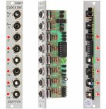
People also bought...
Doepfer A-160-1 Clock/Trigger Divider Module (clock modulator synth module)
Cat: 577765 Rel: 10 Sep 19
Frequency divider for clock, trigger & gate signals - 4HP
Notes: Module A-160 is a frequency divider for clock/trigger/gate signals, designed to be a source of lower frequencies, particularly for rhythm uses. The Trigger input will take clock signals from, e.g. an LFO, MIDI sync, or the gate from a MIDI-CV interface.
At the outputs, you have access to the sub-divided clock signals, from half the clock frequency down to 1/64. The low/high levels of the output signals are 0V and about +10V.
The A-160 also has a reset input. Whenever a reset signal is sensed, all outputs are set to zero, until the reset voltage disappears.
The Clock Divider can be used in combination with the A-161 Clock Sequencer to produce stepped sequences with a length of from one to eight events.
… Read moreAt the outputs, you have access to the sub-divided clock signals, from half the clock frequency down to 1/64. The low/high levels of the output signals are 0V and about +10V.
The A-160 also has a reset input. Whenever a reset signal is sensed, all outputs are set to zero, until the reset voltage disappears.
The Clock Divider can be used in combination with the A-161 Clock Sequencer to produce stepped sequences with a length of from one to eight events.
1 in stock $60.94
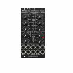
People also bought...
Doepfer A-111-6v Miniature Synthesiser Voice Vintage Edition Module (black) (synth voice synth module)
Cat: 749811 Rel: 15 Nov 19
Complete miniature monophonic synthesiser module - 10HP
Notes: VCO:
- Tune: manual tune control (with an internal jumper the range can be set to ~ +/-1 half an octave or ~ +/-2.5 octaves)
- Oct: range switch -1 / 0 / +1 octave
- Mod: modulation depth (attenuator wired to the Mod. socket)
- Dest: switch that is used to address the modulation to frequency modulation (position FM) or pulsewidth modulation (positon PM), in centre positon no modulation
- PW: manual pulsewidth control for rectangle waveform, PW can be also modulated by the Mod. input as mentioned above
- Wave: waveform switch (sawtooth / off / triangle), the sum of the waveform chosen by this switch and the rectangle is fed into the VCF (to turn the rectangle off the PW control has to be set fully CCW or fully CW)
- 1V/Oct. (socket): external CV input for VCO frequency (1V/octave)
- Access to internal bus CV (via jumper, optional, please remove the bus jumper if this feature is not used to avoid unwanted frequency modulation as then the unused CV line of the bus works as a kind of antenna)
- Triangle core VCO, frequency range about 32Hz ... 8kHz
Balance unit:
- The balance unit is made of two VCAs which are controlled by the sum of manual Balance control and the balance CV input in the opposite direction.
- The audio input of VCA1 is hard-wired to the VCO output, audio input 2 is connected to the socket Ext.In.
- The output of the balance unit is used as audio input for the VCF
- Bal.: manual balance control, fully CCW the internal VCO is used, fully CW the external signal (Ext.In) is used, at centre position both signals have about the same level
- CV Bal.: CV input for balance (range about 0...+5V)
- Ext. In: external audio input for VCA2, about 5 Vpp level required for similar loudness as the internal VCO
- This socket is normalled to the internal VCO suboctave f/2 signal (rectangle with half the frequency), if no external signal is applied the suboctave signal is used as the second signal for the balance unit
VCF:
- 24 dB low pass
- Frq: manual frequency control
- FM1: frequency modulation depth (attenuator wired to the VCF FM1 socket, the socket is normalled to the internal Envelope signal and then FM1 controls the modulation depth of the internal envelope applied to the filter)
- FM2 (socket) : second CV input for VCF without attenuator (about 1V/octave), can be used e.g. for VCF tracking by connecting the same CV which is used also for the VCO frequency
- Res: manual resonance control (up to self oscillation)
- If the VCO is turned off (waveform switch = centre position, pulsewidth control = fully CCW or CW) and the VCF resonance is set to maximum the module can be used as a sine oscillator, the tracking at socket VCF FM2 is about 1V/octave (not as precise as the VCO but much better than most other filters)
- ~ 11 octaves frequency range (~ 10 Hz ... 20kHz)
VCA:
- Gain: manual amplitude control (initial gain), can be used to open the VCA without envelope signal
- VCA (switch): used to switch between gate and envelope as control signal for the VCA, in centre position the VCA is not controlled by envelope or gate
- Note: when gate is used the VCA is controlled directly by the gate signal (i.e. hard on/off), this may lead to clicking noise under certain conditions (especially with low VCO/VCF frequencies)
- Special control scale: exponential scale in the range from about -20dB to -80/90dB, linear scale from about -20dB to 0dB
- Remark: this special control scale results in a loudness behaviour that is a bit different from pure linear or exponential VCAs
- Out: audio output of the module (= VCA output)
Envelope:
- Gate (socket): Gate input (min. +5V), can be normalled to the bus gate signal by means of a jumper
- Att: manual control for Attack
- D/R: manual control for Decay/Release
- Env. (switch): used to switch between A/D, ADSR and A/R mode of the envelope generator, in centre position (ADSR) the sustain level is fixed to about 50%
- Envelope (socket): envelope output (about +10V)
- CVT (socket): CV input for time control, by means of two internal jumpers one can select which time parameters are controlled by the CVT input (e.g. A only or D/R only or A/D/R) and in which direction (i.e. if an increasing CVT shortens or stretches the time parameter in question)
- Envelope LED display
- Attack time range: ~ 1ms ... 5 sec (can be extended by using the CVT input)
- Decay/Release time range: ~ 1ms ... 15 sec (can be extended by using the CVT input)
… Read more- Tune: manual tune control (with an internal jumper the range can be set to ~ +/-1 half an octave or ~ +/-2.5 octaves)
- Oct: range switch -1 / 0 / +1 octave
- Mod: modulation depth (attenuator wired to the Mod. socket)
- Dest: switch that is used to address the modulation to frequency modulation (position FM) or pulsewidth modulation (positon PM), in centre positon no modulation
- PW: manual pulsewidth control for rectangle waveform, PW can be also modulated by the Mod. input as mentioned above
- Wave: waveform switch (sawtooth / off / triangle), the sum of the waveform chosen by this switch and the rectangle is fed into the VCF (to turn the rectangle off the PW control has to be set fully CCW or fully CW)
- 1V/Oct. (socket): external CV input for VCO frequency (1V/octave)
- Access to internal bus CV (via jumper, optional, please remove the bus jumper if this feature is not used to avoid unwanted frequency modulation as then the unused CV line of the bus works as a kind of antenna)
- Triangle core VCO, frequency range about 32Hz ... 8kHz
Balance unit:
- The balance unit is made of two VCAs which are controlled by the sum of manual Balance control and the balance CV input in the opposite direction.
- The audio input of VCA1 is hard-wired to the VCO output, audio input 2 is connected to the socket Ext.In.
- The output of the balance unit is used as audio input for the VCF
- Bal.: manual balance control, fully CCW the internal VCO is used, fully CW the external signal (Ext.In) is used, at centre position both signals have about the same level
- CV Bal.: CV input for balance (range about 0...+5V)
- Ext. In: external audio input for VCA2, about 5 Vpp level required for similar loudness as the internal VCO
- This socket is normalled to the internal VCO suboctave f/2 signal (rectangle with half the frequency), if no external signal is applied the suboctave signal is used as the second signal for the balance unit
VCF:
- 24 dB low pass
- Frq: manual frequency control
- FM1: frequency modulation depth (attenuator wired to the VCF FM1 socket, the socket is normalled to the internal Envelope signal and then FM1 controls the modulation depth of the internal envelope applied to the filter)
- FM2 (socket) : second CV input for VCF without attenuator (about 1V/octave), can be used e.g. for VCF tracking by connecting the same CV which is used also for the VCO frequency
- Res: manual resonance control (up to self oscillation)
- If the VCO is turned off (waveform switch = centre position, pulsewidth control = fully CCW or CW) and the VCF resonance is set to maximum the module can be used as a sine oscillator, the tracking at socket VCF FM2 is about 1V/octave (not as precise as the VCO but much better than most other filters)
- ~ 11 octaves frequency range (~ 10 Hz ... 20kHz)
VCA:
- Gain: manual amplitude control (initial gain), can be used to open the VCA without envelope signal
- VCA (switch): used to switch between gate and envelope as control signal for the VCA, in centre position the VCA is not controlled by envelope or gate
- Note: when gate is used the VCA is controlled directly by the gate signal (i.e. hard on/off), this may lead to clicking noise under certain conditions (especially with low VCO/VCF frequencies)
- Special control scale: exponential scale in the range from about -20dB to -80/90dB, linear scale from about -20dB to 0dB
- Remark: this special control scale results in a loudness behaviour that is a bit different from pure linear or exponential VCAs
- Out: audio output of the module (= VCA output)
Envelope:
- Gate (socket): Gate input (min. +5V), can be normalled to the bus gate signal by means of a jumper
- Att: manual control for Attack
- D/R: manual control for Decay/Release
- Env. (switch): used to switch between A/D, ADSR and A/R mode of the envelope generator, in centre position (ADSR) the sustain level is fixed to about 50%
- Envelope (socket): envelope output (about +10V)
- CVT (socket): CV input for time control, by means of two internal jumpers one can select which time parameters are controlled by the CVT input (e.g. A only or D/R only or A/D/R) and in which direction (i.e. if an increasing CVT shortens or stretches the time parameter in question)
- Envelope LED display
- Attack time range: ~ 1ms ... 5 sec (can be extended by using the CVT input)
- Decay/Release time range: ~ 1ms ... 15 sec (can be extended by using the CVT input)
2 in stock $172.23
People also bought...
Doepfer A-180-3 Dual Buffered Multiple Module (silver) (dual/stereo/multiple synth module)
Cat: 751720 Rel: 23 Oct 19
Dual buffered 1-in-3 multiple module - 4HP
Notes: Module A-180-3 is a dual buffered 1-in-3 multiple. The signal applied to the input socket appears as a buffered signal at the three output sockets. Each output has its own buffer, i.e. the three output sockets are not simply connected to each other. The lower output of the upper unit is normalled in the factory to the input of the lower unit. That way the module works as a single 1-in-6 buffered multiple provided that no signal is applied to the input of the lower unit. But it's also possible to pick-up the bus CV and normalize the input socket of the lower unit to the bus CV.
Application: copying/buffering of CV, gate and audio signals.
… Read moreApplication: copying/buffering of CV, gate and audio signals.
! low stock $51.85
Click for better price!
or call +44 20 7424 1960
quote 751720
quote 751720
