100% Secure Shopping
Studio equipment
Our full range of studio equipment from all the leading equipment and software brands. Guaranteed fast delivery and low prices.
100% Secure Shopping
DJ equipment
Our full range of DJ equipment from all the leading equipment and software brands. Guaranteed fast delivery and low prices. Visit Juno DJ


Filter
Stock

Coming Soon
Equipment
Format
Brand
Featured
Price
Tags
Options
Sort
Price
Price
- Relevance:
- Most relevant
- Bestseller:
- High to low
- Artist:
- A to Z
- Z to A
- Title:
- A to Z
- Z to A
- Label:
- A to Z
- Z to A
- Date:
- Old to new
- New to old
- Price:
- Low to high
- High to low
Items 1 to 18 of 18 on page 1 of 1
People also bought...
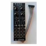
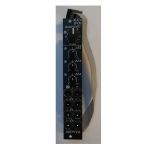
Doepfer A-147-4v Dual VCLFO Dual Voltage Controlled Low Frequency Oscillator Vintage Edition Module (black) (dual/stereo/LFO synth module)
Cat: 950730 Rel: 19 Jun 23 • View all Synth modules
Dual voltage controlled LFO (Low Frequency Oscillator) module - 8HP.
Notes: Module A-147-4V is a dual voltage controlled LFO (Low Frequency Oscillator). Each LFO has the five waveforms triangle, sine, rising and falling sawtooth, as well as rectangle available. The rectangle output features manually adjustable pulsewidth and pulsewidth modulation by means of an external control voltage. The core waveform is triangle. The other waveforms are derived from triangle by means of waveform converters. The frequency of each LFO can be adjusted manually and modulated by means of an external control voltage with associated attenuator and polarity switch. By means of a jumper the basic frequency range of each LFO can selected: about 0.02 Hz (~ 50 seconds) ... 2.5kHz or about 0.0017 Hz(~ 600 seconds) ... 220Hz. That way each LFO can be used also as a VCO with a max. frequency of about 2.5kHz. Each LFO features a reset input which can be used to reset the triangle signal.
The module has these controls and in/outputs available:
Control F : manual control of the frequency, for each LFO the frequency range can be selected by means of a jumper from two values (see technical notes)
frequency coverage of control F in the high frequency range: about 0.075 Hz (~ 13 seconds) ... 1,4kHz
frequency coverage of control F in the low frequency range: about 0.007 Hz (~ 140 seconds) ... 125Hz
Control CV: attenuator for the signal applied to the CV socket, by means of a jumper a small positive voltage can be applied to the switching contact of the /CV/ socket, as long as no patch cable is connected to /CV/ socket the CV control then works as fine control for the frequency
Switch CV Pol.: polarity switch for the signal applied to the socket /CV/
Control PW/PM: combined control for manual and CV control of the rectangle pulsewidth:
when no patch cable is connected to socket /P/ the control is used to adjust the pulsewidth (PW) manually
when a patch cable is connected to socket /P/ the control works as attenuator for the external CV signal with a basic pulsewidth of 50:50.
Socket /CV/: frequency control voltage input, in the factory the module is adjusted so that the sensitivity of this input is exactly 1V/octave when the CV control is fully CW.
Socket /R/: reset input, according to the associated jumper the reset input is edge triggered or level controlled (see technical notes for details)
Socket /P/: pulsewidth control voltage input
Sockets with waveform symbol: output of the waveform in question (triangle, sine, rising and falling sawtooth, rectangle)
The output voltage ranges are about -5V ... +5V (10Vpp), except the rectangle output
For the rectangle output one can choose by means of a jumper if the range is about -5V ... +5V or 0...+10V.
LED: visual control of the LFO (triangle)
The inputs of the module are labelled with white characters on black background (in the text included into two slashes). The outputs are labelled with black characters.
Technical notes and special features:
The basic frequency range of each LFO can be selected by means of a jumper. The settings correspond to two different capacitor values for the VCO circuit. The relation between the two ranges is about 1:11. When the upper range is selected frequencies from about 0.02 Hz up to 2.5kHz can be generated. For the lower range the values are about 0.0017 Hz ... 220Hz. To obtain these full frequency ranges external control voltages are required. With the frequency control F only the frequencies mentioned above are possible.
Apart from that the range for the manual control F can be reduced to obtain a finer resolution. For this a jumper has to be removed. The range of control F is then reduced to about 1:4.5 only.
In the factory the starting voltage of the triangle output after a reset is adjusted to 0V, i.e. the triangle starts from 0V with the rising slope after a reset. By means of a trimming potentiometer the starting voltage can be adjusted to another value (e.g. to -5V).
Another jumper is used to set the reset behaviour to edge triggered or level controlled. When set to edge triggered the rising edge of reset signal is used for the reset (independent of the duration of the "high" state of the reset signal). When set to level controlled the triangle output remains at the starting voltage as long as the reset signal is "high". Only when the reset signal turns "low" the triangle starts.
Power consumption: 80mA at +12 V and 70mA at -12 V
Depth: 45mm
HP : 8
… Read moreThe module has these controls and in/outputs available:
Control F : manual control of the frequency, for each LFO the frequency range can be selected by means of a jumper from two values (see technical notes)
frequency coverage of control F in the high frequency range: about 0.075 Hz (~ 13 seconds) ... 1,4kHz
frequency coverage of control F in the low frequency range: about 0.007 Hz (~ 140 seconds) ... 125Hz
Control CV: attenuator for the signal applied to the CV socket, by means of a jumper a small positive voltage can be applied to the switching contact of the /CV/ socket, as long as no patch cable is connected to /CV/ socket the CV control then works as fine control for the frequency
Switch CV Pol.: polarity switch for the signal applied to the socket /CV/
Control PW/PM: combined control for manual and CV control of the rectangle pulsewidth:
when no patch cable is connected to socket /P/ the control is used to adjust the pulsewidth (PW) manually
when a patch cable is connected to socket /P/ the control works as attenuator for the external CV signal with a basic pulsewidth of 50:50.
Socket /CV/: frequency control voltage input, in the factory the module is adjusted so that the sensitivity of this input is exactly 1V/octave when the CV control is fully CW.
Socket /R/: reset input, according to the associated jumper the reset input is edge triggered or level controlled (see technical notes for details)
Socket /P/: pulsewidth control voltage input
Sockets with waveform symbol: output of the waveform in question (triangle, sine, rising and falling sawtooth, rectangle)
The output voltage ranges are about -5V ... +5V (10Vpp), except the rectangle output
For the rectangle output one can choose by means of a jumper if the range is about -5V ... +5V or 0...+10V.
LED: visual control of the LFO (triangle)
The inputs of the module are labelled with white characters on black background (in the text included into two slashes). The outputs are labelled with black characters.
Technical notes and special features:
The basic frequency range of each LFO can be selected by means of a jumper. The settings correspond to two different capacitor values for the VCO circuit. The relation between the two ranges is about 1:11. When the upper range is selected frequencies from about 0.02 Hz up to 2.5kHz can be generated. For the lower range the values are about 0.0017 Hz ... 220Hz. To obtain these full frequency ranges external control voltages are required. With the frequency control F only the frequencies mentioned above are possible.
Apart from that the range for the manual control F can be reduced to obtain a finer resolution. For this a jumper has to be removed. The range of control F is then reduced to about 1:4.5 only.
In the factory the starting voltage of the triangle output after a reset is adjusted to 0V, i.e. the triangle starts from 0V with the rising slope after a reset. By means of a trimming potentiometer the starting voltage can be adjusted to another value (e.g. to -5V).
Another jumper is used to set the reset behaviour to edge triggered or level controlled. When set to edge triggered the rising edge of reset signal is used for the reset (independent of the duration of the "high" state of the reset signal). When set to level controlled the triangle output remains at the starting voltage as long as the reset signal is "high". Only when the reset signal turns "low" the triangle starts.
Power consumption: 80mA at +12 V and 70mA at -12 V
Depth: 45mm
HP : 8
1 in stock $168.84
Click for better price!
or call +44 20 7424 1960
quote 950730
quote 950730

People also bought...
Doepfer A-111-6v Miniature Synthesiser Voice Vintage Edition Module (black) (B-STOCK) (synth voice synth module)
Cat: 970408 Rel: 01 Jan 90 • View all Synth modules
B-STOCK: Slight dent om the edge, otherwise in perfect condition
Notes: ***B-STOCK: Slight dent om the edge, otherwise in perfect condition***
VCO:
- Tune: manual tune control (with an internal jumper the range can be set to ~ +/-1 half an octave or ~ +/-2.5 octaves)
- Oct: range switch -1 / 0 / +1 octave
- Mod: modulation depth (attenuator wired to the Mod. socket)
- Dest: switch that is used to address the modulation to frequency modulation (position FM) or pulsewidth modulation (positon PM), in centre positon no modulation
- PW: manual pulsewidth control for rectangle waveform, PW can be also modulated by the Mod. input as mentioned above
- Wave: waveform switch (sawtooth / off / triangle), the sum of the waveform chosen by this switch and the rectangle is fed into the VCF (to turn the rectangle off the PW control has to be set fully CCW or fully CW)
- 1V/Oct. (socket): external CV input for VCO frequency (1V/octave)
- Access to internal bus CV (via jumper, optional, please remove the bus jumper if this feature is not used to avoid unwanted frequency modulation as then the unused CV line of the bus works as a kind of antenna)
- Triangle core VCO, frequency range about 32Hz ... 8kHz
Balance unit:
- The balance unit is made of two VCAs which are controlled by the sum of manual Balance control and the balance CV input in the opposite direction.
- The audio input of VCA1 is hard-wired to the VCO output, audio input 2 is connected to the socket Ext.In.
- The output of the balance unit is used as audio input for the VCF
- Bal.: manual balance control, fully CCW the internal VCO is used, fully CW the external signal (Ext.In) is used, at centre position both signals have about the same level
- CV Bal.: CV input for balance (range about 0...+5V)
- Ext. In: external audio input for VCA2, about 5 Vpp level required for similar loudness as the internal VCO
- This socket is normalled to the internal VCO suboctave f/2 signal (rectangle with half the frequency), if no external signal is applied the suboctave signal is used as the second signal for the balance unit
VCF:
- 24 dB low pass
- Frq: manual frequency control
- FM1: frequency modulation depth (attenuator wired to the VCF FM1 socket, the socket is normalled to the internal Envelope signal and then FM1 controls the modulation depth of the internal envelope applied to the filter)
- FM2 (socket) : second CV input for VCF without attenuator (about 1V/octave), can be used e.g. for VCF tracking by connecting the same CV which is used also for the VCO frequency
- Res: manual resonance control (up to self oscillation)
- If the VCO is turned off (waveform switch = centre position, pulsewidth control = fully CCW or CW) and the VCF resonance is set to maximum the module can be used as a sine oscillator, the tracking at socket VCF FM2 is about 1V/octave (not as precise as the VCO but much better than most other filters)
- ~ 11 octaves frequency range (~ 10 Hz ... 20kHz)
VCA:
- Gain: manual amplitude control (initial gain), can be used to open the VCA without envelope signal
- VCA (switch): used to switch between gate and envelope as control signal for the VCA, in centre position the VCA is not controlled by envelope or gate
- Note: when gate is used the VCA is controlled directly by the gate signal (i.e. hard on/off), this may lead to clicking noise under certain conditions (especially with low VCO/VCF frequencies)
- Special control scale: exponential scale in the range from about -20dB to -80/90dB, linear scale from about -20dB to 0dB
- Remark: this special control scale results in a loudness behaviour that is a bit different from pure linear or exponential VCAs
- Out: audio output of the module (= VCA output)
Envelope:
- Gate (socket): Gate input (min. +5V), can be normalled to the bus gate signal by means of a jumper
- Att: manual control for Attack
- D/R: manual control for Decay/Release
- Env. (switch): used to switch between A/D, ADSR and A/R mode of the envelope generator, in centre position (ADSR) the sustain level is fixed to about 50%
- Envelope (socket): envelope output (about +10V)
- CVT (socket): CV input for time control, by means of two internal jumpers one can select which time parameters are controlled by the CVT input (e.g. A only or D/R only or A/D/R) and in which direction (i.e. if an increasing CVT shortens or stretches the time parameter in question)
- Envelope LED display
- Attack time range: ~ 1ms ... 5 sec (can be extended by using the CVT input)
- Decay/Release time range: ~ 1ms ... 15 sec (can be extended by using the CVT input)
… Read moreVCO:
- Tune: manual tune control (with an internal jumper the range can be set to ~ +/-1 half an octave or ~ +/-2.5 octaves)
- Oct: range switch -1 / 0 / +1 octave
- Mod: modulation depth (attenuator wired to the Mod. socket)
- Dest: switch that is used to address the modulation to frequency modulation (position FM) or pulsewidth modulation (positon PM), in centre positon no modulation
- PW: manual pulsewidth control for rectangle waveform, PW can be also modulated by the Mod. input as mentioned above
- Wave: waveform switch (sawtooth / off / triangle), the sum of the waveform chosen by this switch and the rectangle is fed into the VCF (to turn the rectangle off the PW control has to be set fully CCW or fully CW)
- 1V/Oct. (socket): external CV input for VCO frequency (1V/octave)
- Access to internal bus CV (via jumper, optional, please remove the bus jumper if this feature is not used to avoid unwanted frequency modulation as then the unused CV line of the bus works as a kind of antenna)
- Triangle core VCO, frequency range about 32Hz ... 8kHz
Balance unit:
- The balance unit is made of two VCAs which are controlled by the sum of manual Balance control and the balance CV input in the opposite direction.
- The audio input of VCA1 is hard-wired to the VCO output, audio input 2 is connected to the socket Ext.In.
- The output of the balance unit is used as audio input for the VCF
- Bal.: manual balance control, fully CCW the internal VCO is used, fully CW the external signal (Ext.In) is used, at centre position both signals have about the same level
- CV Bal.: CV input for balance (range about 0...+5V)
- Ext. In: external audio input for VCA2, about 5 Vpp level required for similar loudness as the internal VCO
- This socket is normalled to the internal VCO suboctave f/2 signal (rectangle with half the frequency), if no external signal is applied the suboctave signal is used as the second signal for the balance unit
VCF:
- 24 dB low pass
- Frq: manual frequency control
- FM1: frequency modulation depth (attenuator wired to the VCF FM1 socket, the socket is normalled to the internal Envelope signal and then FM1 controls the modulation depth of the internal envelope applied to the filter)
- FM2 (socket) : second CV input for VCF without attenuator (about 1V/octave), can be used e.g. for VCF tracking by connecting the same CV which is used also for the VCO frequency
- Res: manual resonance control (up to self oscillation)
- If the VCO is turned off (waveform switch = centre position, pulsewidth control = fully CCW or CW) and the VCF resonance is set to maximum the module can be used as a sine oscillator, the tracking at socket VCF FM2 is about 1V/octave (not as precise as the VCO but much better than most other filters)
- ~ 11 octaves frequency range (~ 10 Hz ... 20kHz)
VCA:
- Gain: manual amplitude control (initial gain), can be used to open the VCA without envelope signal
- VCA (switch): used to switch between gate and envelope as control signal for the VCA, in centre position the VCA is not controlled by envelope or gate
- Note: when gate is used the VCA is controlled directly by the gate signal (i.e. hard on/off), this may lead to clicking noise under certain conditions (especially with low VCO/VCF frequencies)
- Special control scale: exponential scale in the range from about -20dB to -80/90dB, linear scale from about -20dB to 0dB
- Remark: this special control scale results in a loudness behaviour that is a bit different from pure linear or exponential VCAs
- Out: audio output of the module (= VCA output)
Envelope:
- Gate (socket): Gate input (min. +5V), can be normalled to the bus gate signal by means of a jumper
- Att: manual control for Attack
- D/R: manual control for Decay/Release
- Env. (switch): used to switch between A/D, ADSR and A/R mode of the envelope generator, in centre position (ADSR) the sustain level is fixed to about 50%
- Envelope (socket): envelope output (about +10V)
- CVT (socket): CV input for time control, by means of two internal jumpers one can select which time parameters are controlled by the CVT input (e.g. A only or D/R only or A/D/R) and in which direction (i.e. if an increasing CVT shortens or stretches the time parameter in question)
- Envelope LED display
- Attack time range: ~ 1ms ... 5 sec (can be extended by using the CVT input)
- Decay/Release time range: ~ 1ms ... 15 sec (can be extended by using the CVT input)
1 in stock $163.70
People also bought...
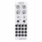
Doepfer A-147-4 Dual VCLFO Dual Voltage Controlled Low Frequency Oscillator Module (silver) (dual/stereo/LFO synth module)
Cat: 945415 Rel: 13 Jun 23 • View all Synth modules
A dual voltage controlled LFO (Low Frequency Oscillator) module in 8HP.
Notes: Module A-147-4 is a dual voltage controlled LFO (Low Frequency Oscillator). Each LFO has the five waveforms triangle, sine, rising and falling sawtooth, as well as rectangle available. The rectangle output features manually adjustable pulsewidth and pulsewidth modulation by means of an external control voltage. The core waveform is triangle. The other waveforms are derived from triangle by means of waveform converters. The frequency of each LFO can be adjusted manually and modulated by means of an external control voltage with associated attenuator and polarity switch. By means of a jumper the basic frequency range of each LFO can selected: about 0.02 Hz (~ 50 seconds) ... 2.5kHz or about 0.0017 Hz(~ 600 seconds) ... 220Hz. That way each LFO can be used also as a VCO with a max. frequency of about 2.5kHz. Each LFO features a reset input which can be used to reset the triangle signal.
The module has these controls and in/outputs available:
Control F : manual control of the frequency, for each LFO the frequency range can be selected by means of a jumper from two values (see technical notes)
frequency coverage of control F in the high frequency range: about 0.075 Hz (~ 13 seconds) ... 1,4kHz
frequency coverage of control F in the low frequency range: about 0.007 Hz (~ 140 seconds) ... 125Hz
Control CV: attenuator for the signal applied to the CV socket, by means of a jumper a small positive voltage can be applied to the switching contact of the /CV/ socket, as long as no patch cable is connected to /CV/ socket the CV control then works as fine control for the frequency
Switch CV Pol.: polarity switch for the signal applied to the socket /CV/
Control PW/PM: combined control for manual and CV control of the rectangle pulsewidth:
when no patch cable is connected to socket /P/ the control is used to adjust the pulsewidth (PW) manually
when a patch cable is connected to socket /P/ the control works as attenuator for the external CV signal with a basic pulsewidth of 50:50.
Socket /CV/: frequency control voltage input, in the factory the module is adjusted so that the sensitivity of this input is exactly 1V/octave when the CV control is fully CW.
Socket /R/: reset input, according to the associated jumper the reset input is edge triggered or level controlled (see technical notes for details)
Socket /P/: pulsewidth control voltage input
Sockets with waveform symbol: output of the waveform in question (triangle, sine, rising and falling sawtooth, rectangle)
The output voltage ranges are about -5V ... +5V (10Vpp), except the rectangle output
For the rectangle output one can choose by means of a jumper if the range is about -5V ... +5V or 0...+10V.
LED: visual control of the LFO (triangle)
The inputs of the module are labelled with white characters on black background (in the text included into two slashes). The outputs are labelled with black characters.
Technical notes and special features:
The basic frequency range of each LFO can be selected by means of a jumper. The settings correspond to two different capacitor values for the VCO circuit. The relation between the two ranges is about 1:11. When the upper range is selected frequencies from about 0.02 Hz up to 2.5kHz can be generated. For the lower range the values are about 0.0017 Hz ... 220Hz. To obtain these full frequency ranges external control voltages are required. With the frequency control F only the frequencies mentioned above are possible.
Apart from that the range for the manual control F can be reduced to obtain a finer resolutuion. For this a jumper has to be removed. The range of control F is then reduced to about 1:4.5 only.
In the factory the starting voltage of the triangle output after a reset is adjusted to 0V, i.e. the triangle starts from 0V with the rising slope after a reset. By means of a trimming potentiometer the starting voltage can be adjusted to another value (e.g. to -5V).
Another jumper is used to set the reset behaviour to edge triggered or level controlled. When set to edge triggered the rising edge of reset signal is used for the reset (independent of the duration of the "high" state of the reset signal). When set to level controlled the triangle output remains at the starting voltage as long as the reset signal is "high". Only when the reset signal turns "low" the triangle starts.
Dimensions
8 HP
45 mm deep
Current Draw
80 mA +12V
70 mA -12V
… Read moreThe module has these controls and in/outputs available:
Control F : manual control of the frequency, for each LFO the frequency range can be selected by means of a jumper from two values (see technical notes)
frequency coverage of control F in the high frequency range: about 0.075 Hz (~ 13 seconds) ... 1,4kHz
frequency coverage of control F in the low frequency range: about 0.007 Hz (~ 140 seconds) ... 125Hz
Control CV: attenuator for the signal applied to the CV socket, by means of a jumper a small positive voltage can be applied to the switching contact of the /CV/ socket, as long as no patch cable is connected to /CV/ socket the CV control then works as fine control for the frequency
Switch CV Pol.: polarity switch for the signal applied to the socket /CV/
Control PW/PM: combined control for manual and CV control of the rectangle pulsewidth:
when no patch cable is connected to socket /P/ the control is used to adjust the pulsewidth (PW) manually
when a patch cable is connected to socket /P/ the control works as attenuator for the external CV signal with a basic pulsewidth of 50:50.
Socket /CV/: frequency control voltage input, in the factory the module is adjusted so that the sensitivity of this input is exactly 1V/octave when the CV control is fully CW.
Socket /R/: reset input, according to the associated jumper the reset input is edge triggered or level controlled (see technical notes for details)
Socket /P/: pulsewidth control voltage input
Sockets with waveform symbol: output of the waveform in question (triangle, sine, rising and falling sawtooth, rectangle)
The output voltage ranges are about -5V ... +5V (10Vpp), except the rectangle output
For the rectangle output one can choose by means of a jumper if the range is about -5V ... +5V or 0...+10V.
LED: visual control of the LFO (triangle)
The inputs of the module are labelled with white characters on black background (in the text included into two slashes). The outputs are labelled with black characters.
Technical notes and special features:
The basic frequency range of each LFO can be selected by means of a jumper. The settings correspond to two different capacitor values for the VCO circuit. The relation between the two ranges is about 1:11. When the upper range is selected frequencies from about 0.02 Hz up to 2.5kHz can be generated. For the lower range the values are about 0.0017 Hz ... 220Hz. To obtain these full frequency ranges external control voltages are required. With the frequency control F only the frequencies mentioned above are possible.
Apart from that the range for the manual control F can be reduced to obtain a finer resolutuion. For this a jumper has to be removed. The range of control F is then reduced to about 1:4.5 only.
In the factory the starting voltage of the triangle output after a reset is adjusted to 0V, i.e. the triangle starts from 0V with the rising slope after a reset. By means of a trimming potentiometer the starting voltage can be adjusted to another value (e.g. to -5V).
Another jumper is used to set the reset behaviour to edge triggered or level controlled. When set to edge triggered the rising edge of reset signal is used for the reset (independent of the duration of the "high" state of the reset signal). When set to level controlled the triangle output remains at the starting voltage as long as the reset signal is "high". Only when the reset signal turns "low" the triangle starts.
Dimensions
8 HP
45 mm deep
Current Draw
80 mA +12V
70 mA -12V
1 in stock $156.65
People also bought...
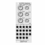
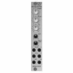
Doepfer A-135-5 Polyphonic Voltage Controlled Mixer/Suboctave Generator Module (mixer synth module)
Cat: 945421 Rel: 19 Oct 23 • View all Synth modules
Polyphonic voltage controlled mixer & suboctave generator module - 10HP.
Notes: Module A-135-5 is a combination of a voltage controlled polyphonic mixer and a polyphonic suboctave generator. It is made of 12 voltage controlled amplifiers (VCAs) which are arranged in form of a 4x3 matrix. Herewith up to three four-voice polyphonic signals (e.g. the outputs of three polyphonic VCOs A-111-4) can be mixed. The level of each of the three polyphonic channels (A, B, C) with four voices each can be controlled manually or by means of an external control voltage with associated attenuators.
In addition the module features four frequency dividers which derive the suboctaves from the four input signals of channel A. The suboctave signals are wired to the switching contacts of the sockets of channel B. As long as the sockets of channel B are not patched the suboctave signals of channel A are used as inputs for channel B. The suboctaves are symmetrical rectangle waves with half the frequency of the corresponding signal A. For example two polyphonic VCOs A-111-4) can be used and patched to the channels A and C. Channel B then provides the suboctaves of channel A.
As the module is fully DC coupled it can be used also for the mixing of control voltages in a polyphonic environment (e.g. for envelopes, LFOs or other control voltages).
The switching contacts of the 12 input sockets and the four outputs are internally connected to pin headers. That way the module can be internally pre-patched to other polyphonic modules (e.g. the four inputs A to an A-111-4, the four inputs C to another A-111-4 and the outputs to the polyphonic filter A-105-4). As the switching contacts of the sockets are used for the internal pre-patching the internal patch can be overridden by using the sockets at the front panel.
The module has these controls and in/outputs available:
Controls Lev.A, Lev.B, Lev.C: manual level adjustment of the channels A, B and C
Controls CV A, CV B, CV C: attenuators for the corresponding control voltage inputs
Sockets A1...4: inputs channel A
Sockets B1...4: inputs channel B (if the sockets are not patched the suboctave signals are used for the inputs B)
Sockets C1...4: inputs channel C
Sockets CV A. CV B, CV C: control voltage inputs for the channels A, B and C
Sockets Out 1...4: outputs
Dimensions
10 HP
55 mm deep
… Read moreIn addition the module features four frequency dividers which derive the suboctaves from the four input signals of channel A. The suboctave signals are wired to the switching contacts of the sockets of channel B. As long as the sockets of channel B are not patched the suboctave signals of channel A are used as inputs for channel B. The suboctaves are symmetrical rectangle waves with half the frequency of the corresponding signal A. For example two polyphonic VCOs A-111-4) can be used and patched to the channels A and C. Channel B then provides the suboctaves of channel A.
As the module is fully DC coupled it can be used also for the mixing of control voltages in a polyphonic environment (e.g. for envelopes, LFOs or other control voltages).
The switching contacts of the 12 input sockets and the four outputs are internally connected to pin headers. That way the module can be internally pre-patched to other polyphonic modules (e.g. the four inputs A to an A-111-4, the four inputs C to another A-111-4 and the outputs to the polyphonic filter A-105-4). As the switching contacts of the sockets are used for the internal pre-patching the internal patch can be overridden by using the sockets at the front panel.
The module has these controls and in/outputs available:
Controls Lev.A, Lev.B, Lev.C: manual level adjustment of the channels A, B and C
Controls CV A, CV B, CV C: attenuators for the corresponding control voltage inputs
Sockets A1...4: inputs channel A
Sockets B1...4: inputs channel B (if the sockets are not patched the suboctave signals are used for the inputs B)
Sockets C1...4: inputs channel C
Sockets CV A. CV B, CV C: control voltage inputs for the channels A, B and C
Sockets Out 1...4: outputs
Dimensions
10 HP
55 mm deep
out of stock $148.25
People also bought...
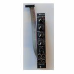
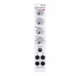
Doepfer A-101-8v Photo Phasing 8-Stage Phase Shifter Vintage Edition Module (black) (phase shifter/effect synth module)
Cat: 950741 Rel: 19 Jun 23 • View all Synth modules
8-stage phase shifter module - 4HP.
Notes: Module A-101-8V is a 8-stage phase shifter which uses light-sensitive resistors (LDR) and is a replica of the Compact Phasing A manufactured by the company Schulte in the seventies. The actual phasing circuit is identical to the historic model. Only the illumination control of the LDRs is different: the A-101-8 uses LEDs to illuminate the LDRs, the historic model used incandescent miniature lamps. And the A-101-8 has no built-in LFO but can be controlled by any external control voltage source (e.g. LFO, ADSR, random, Theremin, ribbon controller, sequencer, midi). The phasing offset (i.e. the base value for the phase shifting) and the modulation depth of the external control signal can be adjusted separately. The Compact Phasing A had no offset control but only a depth control for the built-in LFO. Feedback and mixing ratio of the output signal are set by two controls. The audio input is equipped with an attenuator. The module has two audio outputs available (same as the historic model) and a visual display of the phase shifting.
The module has these controls and in/outputs available:
Control Man. : manual control of the phase shift offset (base value)
Control CV: attenuator for the signal applied to the CV socket
Control Feedb.: Feedback or Resonance (similar function as filter resonance/feedback/emphasis)
Control Mix: sets the mixing ratio between original and phase shift signal appearing at output 1
fully CCW: only the modified input signal appears at output 1 (see note below *)
center: a mixture between the modified input signal and the phase shift signal appears at output 1, that's the standard position for the classical phasing effect
fully CW: the pure phase shifted signal appears at output 1 (e.g. for vibrato effects)
Control Input Level: attenuator for signal applied to the In socket
Socket In: audio input
Socket CV: control voltage input
Socket Out 1: audio output 1 (mix signal)
Socket Out 2: audio output 2 (modified input signal)
LED: visual control of the phase shift
The module has some peculiarities (same as the historic model):
The input signal is processed at first by a pre-stage which outputs a "modified" input signal (*). This signal is not processed by the phase shift stages but is affected by the feedback setting. Only when feedback is set to zero this signal is identical to the input signal. Otherwise it contains feedback components.
This signal is output on socket Out 2.
When both output sockets Out 1 and Out 2 are used as stereo channels one obtains a spatial stereo sound effect.
The same signals is also used for the CCW position of the mix control. With mix control fully CCW the unmodified signal appears only if the feedback control is set to zero. Otherwise it contains feedback components.
The historic model had two audio inputs: one 5-pin DIN socket and a 1/4" jack socket. The DIN socket was intended for high-level line signals. When the 1/4" jack socket was used the amplification of the pre-stage increased by about 100. The 1/4" jack socket was intended for low level signals (e.g. electric guitars or microphones). For this feature the A-101-8 has an internal jumper that can be used to increase the amplification. As long as the module is used within the A-100 system usually the lower amplification is used to avoid distortion.
The 8 photo resistors and LEDs are assembled within an small lightproof box. In addition the pc boards are made of lightproof black material to avoid interfering light from other modules or the bus board.
Power consumption: 30mA at +12 V and 30mA at -12 V
Depth: 45mm
HP : 4
… Read moreThe module has these controls and in/outputs available:
Control Man. : manual control of the phase shift offset (base value)
Control CV: attenuator for the signal applied to the CV socket
Control Feedb.: Feedback or Resonance (similar function as filter resonance/feedback/emphasis)
Control Mix: sets the mixing ratio between original and phase shift signal appearing at output 1
fully CCW: only the modified input signal appears at output 1 (see note below *)
center: a mixture between the modified input signal and the phase shift signal appears at output 1, that's the standard position for the classical phasing effect
fully CW: the pure phase shifted signal appears at output 1 (e.g. for vibrato effects)
Control Input Level: attenuator for signal applied to the In socket
Socket In: audio input
Socket CV: control voltage input
Socket Out 1: audio output 1 (mix signal)
Socket Out 2: audio output 2 (modified input signal)
LED: visual control of the phase shift
The module has some peculiarities (same as the historic model):
The input signal is processed at first by a pre-stage which outputs a "modified" input signal (*). This signal is not processed by the phase shift stages but is affected by the feedback setting. Only when feedback is set to zero this signal is identical to the input signal. Otherwise it contains feedback components.
This signal is output on socket Out 2.
When both output sockets Out 1 and Out 2 are used as stereo channels one obtains a spatial stereo sound effect.
The same signals is also used for the CCW position of the mix control. With mix control fully CCW the unmodified signal appears only if the feedback control is set to zero. Otherwise it contains feedback components.
The historic model had two audio inputs: one 5-pin DIN socket and a 1/4" jack socket. The DIN socket was intended for high-level line signals. When the 1/4" jack socket was used the amplification of the pre-stage increased by about 100. The 1/4" jack socket was intended for low level signals (e.g. electric guitars or microphones). For this feature the A-101-8 has an internal jumper that can be used to increase the amplification. As long as the module is used within the A-100 system usually the lower amplification is used to avoid distortion.
The 8 photo resistors and LEDs are assembled within an small lightproof box. In addition the pc boards are made of lightproof black material to avoid interfering light from other modules or the bus board.
Power consumption: 30mA at +12 V and 30mA at -12 V
Depth: 45mm
HP : 4
out of stock $142.07
People also bought...
Doepfer A-105-2v 24dB Low Pass (SSI-Type) Filter Vintage Edition Module (black) (filter/oscillator synth module)
Cat: 973745 Rel: 14 Nov 23 • View all Synth modules
24dB SSI low pass filter module - 4HP.
Notes: Module A-105-2V is a voltage controlled low pass filter with 24dB/octave slope.
It is the successor of the A-105 which had to be discontinued because the obsolete SSM2044 filter circuit. The A-105-2 is based on the SSI2144 which is in turn the successor circuit of the SSM2044. The features of both modules are nearly the same. The main difference is the clearly reduced front panel width of the A-105-2 (4HP instead of 8HP) and the associated changes of the controls and sockets positions. In addition the A-105-2 is equipped with 2 audio inputs.
The module has these controls and in/outputs available:
Control Frequ: manual frequency control
Control FCV2: attenuator for the frequency control voltage applied to socket FCV2
Control Q: manual resonance control
Control QCV: attenuator for the resonance control voltage applied to socket QCV
Control Input 1 Level: attenuator for the audio input signal applied to socket Input 1
Socket Input 1: audio input 1 (with attenuator)
Socket Input 2: audio input 2 (without attenuator)
Socket FCV1: frequency control voltage 1 (without attenuator, about 1V/oct scale)
Socket FCV2: frequency control voltage 2 (with attenuator)
Socket QCV: resonance control voltage (with attenuator)
Socket Out: audio output
Technical notes:
Frequency range: about 15Hz ... 15 kHz
Resonance up to self oscillation
Max. input voltage at Input 2 without clipping/distortion: about 15Vpp
Max. output voltage without clipping/distortion: about 15Vpp
The signals of both inputs are mixed before they are processed by the filter. This saves an external mixer for small setups.
Depth: 45 mm
HP : 4
… Read moreIt is the successor of the A-105 which had to be discontinued because the obsolete SSM2044 filter circuit. The A-105-2 is based on the SSI2144 which is in turn the successor circuit of the SSM2044. The features of both modules are nearly the same. The main difference is the clearly reduced front panel width of the A-105-2 (4HP instead of 8HP) and the associated changes of the controls and sockets positions. In addition the A-105-2 is equipped with 2 audio inputs.
The module has these controls and in/outputs available:
Control Frequ: manual frequency control
Control FCV2: attenuator for the frequency control voltage applied to socket FCV2
Control Q: manual resonance control
Control QCV: attenuator for the resonance control voltage applied to socket QCV
Control Input 1 Level: attenuator for the audio input signal applied to socket Input 1
Socket Input 1: audio input 1 (with attenuator)
Socket Input 2: audio input 2 (without attenuator)
Socket FCV1: frequency control voltage 1 (without attenuator, about 1V/oct scale)
Socket FCV2: frequency control voltage 2 (with attenuator)
Socket QCV: resonance control voltage (with attenuator)
Socket Out: audio output
Technical notes:
Frequency range: about 15Hz ... 15 kHz
Resonance up to self oscillation
Max. input voltage at Input 2 without clipping/distortion: about 15Vpp
Max. output voltage without clipping/distortion: about 15Vpp
The signals of both inputs are mixed before they are processed by the filter. This saves an external mixer for small setups.
Depth: 45 mm
HP : 4
1 in stock $123.54
Click for better price!
or call +44 20 7424 1960
quote 973745
quote 973745
People also bought...
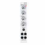
Doepfer A-101-8 Photo Phasing 8-Stage Phase Shifter Module (silver) (phase shifter/effect synth module)
Cat: 945411 Rel: 13 Jun 23 • View all Synth modules
An eight stage phase shifter module in 4HP.
Notes: Module A-101-8 is a 8-stage phase shifter which uses light-sensitive resistors (LDR) and is a replica of the Compact Phasing A manufactured by the company Schulte in the seventies. The actual phasing circuit is identical to the historic model. Only the illumination control of the LDRs is different: the A-101-8 uses LEDs to illuminate the LDRs, the historic model used incandescent miniature lamps. And the A-101-8 has no built-in LFO but can be controlled by any external control voltage source (e.g. LFO, ADSR, random, Theremin, ribbon controller, sequencer, midi). The phasing offset (i.e. the base value for the phase shifting) and the modulation depth of the external control signal can be adjusted separately. The Compact Phasing A had no offset control but only a depth control for the built-in LFO. Feedback and mixing ratio of the output signal are set by two controls. The audio input is equipped with an attenuator. The module has two audio outputs available (same as the historic model) and a visual display of the phase shifting.
The module has these controls and in/outputs available:
Control Man. : manual control of the phase shift offset (base value)
Control CV: attenuator for the signal applied to the CV socket
Control Feedb.: Feedback or Resonance (similar function as filter resonance/feedback/emphasis)
Control Mix: sets the mixing ratio between original and phase shift signal appearing at output 1
fully CCW: only the modified input signal appears at output 1 (see note below *)
center: a mixture between the modified input signal and the phase shift signal appears at output 1, that's the standard position for the classical phasing effect
fully CW: the pure phase shifted signal appears at output 1 (e.g. for vibrato effects)
Control Input Level: attenuator for signal applied to the In socket
Socket In: audio input
Socket CV: control voltage input
Socket Out 1: audio output 1 (mix signal)
Socket Out 2: audio output 2 (modified input signal)
LED: visual control of the phase shift
The module has some peculiarities (same as the historic model):
The input signal is processed at first by a pre-stage which outputs a "modified" input signal (*). This signal is not processed by the phase shift stages but is affected by the feedback setting. Only when feedback is set to zero this signal is identical to the input signal. Otherwise it contains feedback components.
This signal is output on socket Out 2.
When both output sockets Out 1 and Out 2 are used as stereo channels one obtains a spatial stereo sound effect.
The same signals is also used for the CCW position of the mix control. With mix control fully CCW the unmodified signal appears only if the feedback control is set to zero. Otherwise it contains feedback components.
The historic model had two audio inputs: one 5-pin DIN socket and a 1/4" jack socket. The DIN socket was intended for high-level line signals. When the 1/4" jack socket was used the amplification of the pre-stage increased by about 100. The 1/4" jack socket was intended for low level signals (e.g. electric guitars or microphones). For this feature the A-101-8 has an internal jumper that can be used to increase the amplification. As long as the module is used within the A-100 system usually the lower amplification is used to avoid distortion.
The 8 photo resistors and LEDs are assembled within an small lighproof box. In addition the pc boards are made of lighproof black material to avoid interfering light from other modules or the bus board.
Dimensions
4 HP
45 mm deep
Current Draw
30 mA +12V
30 mA -12V
… Read moreThe module has these controls and in/outputs available:
Control Man. : manual control of the phase shift offset (base value)
Control CV: attenuator for the signal applied to the CV socket
Control Feedb.: Feedback or Resonance (similar function as filter resonance/feedback/emphasis)
Control Mix: sets the mixing ratio between original and phase shift signal appearing at output 1
fully CCW: only the modified input signal appears at output 1 (see note below *)
center: a mixture between the modified input signal and the phase shift signal appears at output 1, that's the standard position for the classical phasing effect
fully CW: the pure phase shifted signal appears at output 1 (e.g. for vibrato effects)
Control Input Level: attenuator for signal applied to the In socket
Socket In: audio input
Socket CV: control voltage input
Socket Out 1: audio output 1 (mix signal)
Socket Out 2: audio output 2 (modified input signal)
LED: visual control of the phase shift
The module has some peculiarities (same as the historic model):
The input signal is processed at first by a pre-stage which outputs a "modified" input signal (*). This signal is not processed by the phase shift stages but is affected by the feedback setting. Only when feedback is set to zero this signal is identical to the input signal. Otherwise it contains feedback components.
This signal is output on socket Out 2.
When both output sockets Out 1 and Out 2 are used as stereo channels one obtains a spatial stereo sound effect.
The same signals is also used for the CCW position of the mix control. With mix control fully CCW the unmodified signal appears only if the feedback control is set to zero. Otherwise it contains feedback components.
The historic model had two audio inputs: one 5-pin DIN socket and a 1/4" jack socket. The DIN socket was intended for high-level line signals. When the 1/4" jack socket was used the amplification of the pre-stage increased by about 100. The 1/4" jack socket was intended for low level signals (e.g. electric guitars or microphones). For this feature the A-101-8 has an internal jumper that can be used to increase the amplification. As long as the module is used within the A-100 system usually the lower amplification is used to avoid distortion.
The 8 photo resistors and LEDs are assembled within an small lighproof box. In addition the pc boards are made of lighproof black material to avoid interfering light from other modules or the bus board.
Dimensions
4 HP
45 mm deep
Current Draw
30 mA +12V
30 mA -12V
7 in stock $123.03
Click for better price!
or call +44 20 7424 1960
quote 945411
quote 945411
People also bought...
Doepfer A-101-8 Photo Phasing 8-Stage Phase Shifter Module (silver) (B-STOCK) (phase shifter/effect synth module)
Cat: 966281 Rel: 01 Jan 90 • View all Synth modules
B-STOCK: Box opened, but product is in excellent condition and in perfect working order
Notes: ***B-STOCK: Box opened, but product is in excellent condition and in perfect working order***
Module A-101-8 is a 8-stage phase shifter which uses light-sensitive resistors (LDR) and is a replica of the Compact Phasing A manufactured by the company Schulte in the seventies. The actual phasing circuit is identical to the historic model. Only the illumination control of the LDRs is different: the A-101-8 uses LEDs to illuminate the LDRs, the historic model used incandescent miniature lamps. And the A-101-8 has no built-in LFO but can be controlled by any external control voltage source (e.g. LFO, ADSR, random, Theremin, ribbon controller, sequencer, midi). The phasing offset (i.e. the base value for the phase shifting) and the modulation depth of the external control signal can be adjusted separately. The Compact Phasing A had no offset control but only a depth control for the built-in LFO. Feedback and mixing ratio of the output signal are set by two controls. The audio input is equipped with an attenuator. The module has two audio outputs available (same as the historic model) and a visual display of the phase shifting.
The module has these controls and in/outputs available:
Control Man. : manual control of the phase shift offset (base value)
Control CV: attenuator for the signal applied to the CV socket
Control Feedb.: Feedback or Resonance (similar function as filter resonance/feedback/emphasis)
Control Mix: sets the mixing ratio between original and phase shift signal appearing at output 1
fully CCW: only the modified input signal appears at output 1 (see note below *)
center: a mixture between the modified input signal and the phase shift signal appears at output 1, that's the standard position for the classical phasing effect
fully CW: the pure phase shifted signal appears at output 1 (e.g. for vibrato effects)
Control Input Level: attenuator for signal applied to the In socket
Socket In: audio input
Socket CV: control voltage input
Socket Out 1: audio output 1 (mix signal)
Socket Out 2: audio output 2 (modified input signal)
LED: visual control of the phase shift
The module has some peculiarities (same as the historic model):
The input signal is processed at first by a pre-stage which outputs a "modified" input signal (*). This signal is not processed by the phase shift stages but is affected by the feedback setting. Only when feedback is set to zero this signal is identical to the input signal. Otherwise it contains feedback components.
This signal is output on socket Out 2.
When both output sockets Out 1 and Out 2 are used as stereo channels one obtains a spatial stereo sound effect.
The same signals is also used for the CCW position of the mix control. With mix control fully CCW the unmodified signal appears only if the feedback control is set to zero. Otherwise it contains feedback components.
The historic model had two audio inputs: one 5-pin DIN socket and a 1/4" jack socket. The DIN socket was intended for high-level line signals. When the 1/4" jack socket was used the amplification of the pre-stage increased by about 100. The 1/4" jack socket was intended for low level signals (e.g. electric guitars or microphones). For this feature the A-101-8 has an internal jumper that can be used to increase the amplification. As long as the module is used within the A-100 system usually the lower amplification is used to avoid distortion.
The 8 photo resistors and LEDs are assembled within an small lighproof box. In addition the pc boards are made of lighproof black material to avoid interfering light from other modules or the bus board.
Dimensions
4 HP
45 mm deep
Current Draw
30 mA +12V
30 mA -12V
… Read moreModule A-101-8 is a 8-stage phase shifter which uses light-sensitive resistors (LDR) and is a replica of the Compact Phasing A manufactured by the company Schulte in the seventies. The actual phasing circuit is identical to the historic model. Only the illumination control of the LDRs is different: the A-101-8 uses LEDs to illuminate the LDRs, the historic model used incandescent miniature lamps. And the A-101-8 has no built-in LFO but can be controlled by any external control voltage source (e.g. LFO, ADSR, random, Theremin, ribbon controller, sequencer, midi). The phasing offset (i.e. the base value for the phase shifting) and the modulation depth of the external control signal can be adjusted separately. The Compact Phasing A had no offset control but only a depth control for the built-in LFO. Feedback and mixing ratio of the output signal are set by two controls. The audio input is equipped with an attenuator. The module has two audio outputs available (same as the historic model) and a visual display of the phase shifting.
The module has these controls and in/outputs available:
Control Man. : manual control of the phase shift offset (base value)
Control CV: attenuator for the signal applied to the CV socket
Control Feedb.: Feedback or Resonance (similar function as filter resonance/feedback/emphasis)
Control Mix: sets the mixing ratio between original and phase shift signal appearing at output 1
fully CCW: only the modified input signal appears at output 1 (see note below *)
center: a mixture between the modified input signal and the phase shift signal appears at output 1, that's the standard position for the classical phasing effect
fully CW: the pure phase shifted signal appears at output 1 (e.g. for vibrato effects)
Control Input Level: attenuator for signal applied to the In socket
Socket In: audio input
Socket CV: control voltage input
Socket Out 1: audio output 1 (mix signal)
Socket Out 2: audio output 2 (modified input signal)
LED: visual control of the phase shift
The module has some peculiarities (same as the historic model):
The input signal is processed at first by a pre-stage which outputs a "modified" input signal (*). This signal is not processed by the phase shift stages but is affected by the feedback setting. Only when feedback is set to zero this signal is identical to the input signal. Otherwise it contains feedback components.
This signal is output on socket Out 2.
When both output sockets Out 1 and Out 2 are used as stereo channels one obtains a spatial stereo sound effect.
The same signals is also used for the CCW position of the mix control. With mix control fully CCW the unmodified signal appears only if the feedback control is set to zero. Otherwise it contains feedback components.
The historic model had two audio inputs: one 5-pin DIN socket and a 1/4" jack socket. The DIN socket was intended for high-level line signals. When the 1/4" jack socket was used the amplification of the pre-stage increased by about 100. The 1/4" jack socket was intended for low level signals (e.g. electric guitars or microphones). For this feature the A-101-8 has an internal jumper that can be used to increase the amplification. As long as the module is used within the A-100 system usually the lower amplification is used to avoid distortion.
The 8 photo resistors and LEDs are assembled within an small lighproof box. In addition the pc boards are made of lighproof black material to avoid interfering light from other modules or the bus board.
Dimensions
4 HP
45 mm deep
Current Draw
30 mA +12V
30 mA -12V
out of stock $111.63
People also bought...
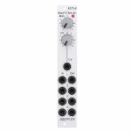
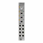
Doepfer A-171-4 Quad Voltage Controlled Slew Limiter Module (quad/slew limiter synth module)
Cat: 945417 Rel: 13 Jun 23 • View all Synth modules
A quad voltage controlled slew limiter (polyphonic portamento) module in 4HP.
Notes: Module A-171-4 is a fourfold voltage controlled slew limiter. It's intended purpose is polyphonic portamento but can be used also for other applications where several slew limiters are required.
The common slew time can be adjusted manually and in addition controlled by an external control voltage. The module uses light-sensitive resistors (LDR). Therefore the slew times are not exactly the same for all units due to the tolerances of the LDRs and the LEDs, which are used to illuminate the LDRs. Inputs and outputs of the slew limiters are buffered to avoid voltage drops. This is especially important for polyphonic portamento applications. Each output can drive several VCOs without the need of external buffers. In addition the slew limiter inputs and outputs are available at internal pin headers for internal pre-wiring of polyphonic patches. As the switching contacts of the sockets are used for the internal pre-patching the internal patch can be overridden by using the sockets at the front panel.
The module has these controls and in/outputs available:
Control Man. : manual control of the slew limiter value (base value)
Control CV: attenuator for the signal applied to the CV socket
Socket CV: control voltage input
Sockets In 1...4: slew limiter inputs
Sockets Out 1...4: slew limiter outputs
LED: visual control of the slew limiter value (dark = long time, bright = short time)
Technical notes:
Each light-sensitive resistor (LDR) forms together with an associated capacitor a simple standard RC network (Resistor/Capacitor network). Input and output of each network are buffered.
The slew time range is about 5 ms ... 10 s (1:2000). Due to the tolerances of the LDRs and the LEDs the slew times vary a bit for each unit. By changing the capacitor values this range can be altered: by lowering the capacitor values the slew limiters can be used as 6dB low pass filters. Increasing the capacitor values result in longer slew times
The 4 photo resistors and LEDs are assembled within an small lighproof box. In addition the pc boards are made of lighproof black material to avoid interfering light from other modules or the bus board.
On the module pc boards two pin headers with 4 pins each are available. These are planned for the internal pre-patching of polyphonic modules:
In 1...4: The pins of this pin header are connected to the switching contacts of the sockets In 1...4. Hereby an internal four-wire connection to the CV outputs of the polyphonic midi-CV-interface A-190-5 can be made. As long as the sockets In 1...4 are not used the internal connection to the A-190-5 is established.
Out 1...4: The pins of this pin header are connected to the outputs Out 1...4. Hereby an internal four-wire connection to the CV inputs of the polyphonic VCO A-111-4 can be realized. If more than one VCO has to be controlled by one output we offer so-called micro multiples.
Dimensions
4 HP
45 mm deep
Current Draw
40 mA +12V
40 mA -12V
… Read moreThe common slew time can be adjusted manually and in addition controlled by an external control voltage. The module uses light-sensitive resistors (LDR). Therefore the slew times are not exactly the same for all units due to the tolerances of the LDRs and the LEDs, which are used to illuminate the LDRs. Inputs and outputs of the slew limiters are buffered to avoid voltage drops. This is especially important for polyphonic portamento applications. Each output can drive several VCOs without the need of external buffers. In addition the slew limiter inputs and outputs are available at internal pin headers for internal pre-wiring of polyphonic patches. As the switching contacts of the sockets are used for the internal pre-patching the internal patch can be overridden by using the sockets at the front panel.
The module has these controls and in/outputs available:
Control Man. : manual control of the slew limiter value (base value)
Control CV: attenuator for the signal applied to the CV socket
Socket CV: control voltage input
Sockets In 1...4: slew limiter inputs
Sockets Out 1...4: slew limiter outputs
LED: visual control of the slew limiter value (dark = long time, bright = short time)
Technical notes:
Each light-sensitive resistor (LDR) forms together with an associated capacitor a simple standard RC network (Resistor/Capacitor network). Input and output of each network are buffered.
The slew time range is about 5 ms ... 10 s (1:2000). Due to the tolerances of the LDRs and the LEDs the slew times vary a bit for each unit. By changing the capacitor values this range can be altered: by lowering the capacitor values the slew limiters can be used as 6dB low pass filters. Increasing the capacitor values result in longer slew times
The 4 photo resistors and LEDs are assembled within an small lighproof box. In addition the pc boards are made of lighproof black material to avoid interfering light from other modules or the bus board.
On the module pc boards two pin headers with 4 pins each are available. These are planned for the internal pre-patching of polyphonic modules:
In 1...4: The pins of this pin header are connected to the switching contacts of the sockets In 1...4. Hereby an internal four-wire connection to the CV outputs of the polyphonic midi-CV-interface A-190-5 can be made. As long as the sockets In 1...4 are not used the internal connection to the A-190-5 is established.
Out 1...4: The pins of this pin header are connected to the outputs Out 1...4. Hereby an internal four-wire connection to the CV inputs of the polyphonic VCO A-111-4 can be realized. If more than one VCO has to be controlled by one output we offer so-called micro multiples.
Dimensions
4 HP
45 mm deep
Current Draw
40 mA +12V
40 mA -12V
out of stock $111.18
People also bought...
Doepfer A-147-5v Quad VCLFO Vintage Edition Module (black) (LFO synth module)
Cat: 973760 Rel: 14 Nov 23 • View all Synth modules
Quad VCLFO module - 4HP.
Notes: Module A-147-5v contains four voltage controlled low frequency oscillators (VCLFO) with triangle waveform outputs. All LFOs share a common frequency control. Each of the LFOs 2, 3 features a Delta control which is used to shift the frequency of the LFO in question up or down. With the Delta controls at center positions the frequencies of all LFOs are roughly the same. To control the frequencies by external control voltages four CV inputs are available which follow roughly the 1V/oct standard.
The module has these controls and in/outputs available:
Control F: manual control of the frequency for all four LFOs
Control Delta F2, F3 and F4: manual control of the frequency shift up/down for the LFO in question
Sockets CV 1...4: Frequency control voltage inputs (normalled from top to bottom)
Sockets with triangle symbol 1...4: triangle outputs
LEDs: visual displays of the triangle outputs (red = positive, yellow = negative output voltage)
Application examples:
Generation of four triangle modulation signals with a common frequency control for all LFOs and individual controls for the frequency deviation of each LFO, manually adjustable and controllable by external control voltages
Generation of modulation signals for polyphonic FM/PWM applications. For this the four CV inputs are connected to the same control voltages which are used to control the frequencies of the corresponding VCOs. That way each LFO follows the frequency of the associated VCO with the possibility to control the frequency of all VCOs (control F) and the frequency deviations (Delta F controls). For the simultaneous modulation depth control the Quad VCA module A-130-4 is recommended.
Generation of complex modulation signals by summing up the outputs (e.g. by means of a mixer module A-138n / A-138i / A-138j)
Technical notes:
The level of the triangle outputs is about +/-5V (10Vpp)
The manually adjustable frequency ranges from about 0.025 Hz (about 40 seconds) to about 50 Hz with the delta controls of LFOs 2, 3 and 4 about center position
The frequency deviations adjusted by the delta controls are about +/-1:5. Example: with 1 Hz in center position the frequency shift ranges from about 0.2 Hz in position -5 to about 5 Hz in position +5 (1 Hz/5 = 0.2 Hz, 1 Hz*5 = 5 Hz).
The manual frequency controls and the control voltage inputs have an exponential control behavior
With external control voltage the max. frequency is about 150 Hz, the minimum frequency
The scale of the CV inputs is roughly 1V/oct (not adjustable)
The CV inputs are normalled from top to bottom. Provided that only socket CV1 is patched CV1 controls the frequencies of all four LFOs.
When each CV input is patched to it's own control voltage each LFO is controlled individually by it's own CV. In this case CV1 controls only the frequency of LFO1.
Internally the rectangle outputs are available at four terminals (typ level +/-10V or 20Vpp). If required they can be wired to four sockets of a DIY breakout module made by the user, 1k protection resistors are recommended to avoid short circuits. If lower levels are required passive attenuators (voltage dividers) may be used.
Internally is even an (unbufferd) triangle sum signal available. For this each of the four triangle outputs is simply connected to the sum output terminal via a 47k resistor. This output has high impedance and should be buffered or amplified to avoid level drop when the load changes (e.g. by means of an A-180-3 or A-180-4 or A-183-3).
By changing the values of the capacitors in the LFO circuits even other frequency ranges are possible (e.g. Quad VCO to form kind of a cloud VCO). Pay attention that the accuracy of the CV input scales is not sufficient for precise 1V/oct VCO applications. The 1V/Oct scales cannot be adjusted and the circuits are not temperature compensated.
Dimensions
4 HP
45 mm deep
… Read moreThe module has these controls and in/outputs available:
Control F: manual control of the frequency for all four LFOs
Control Delta F2, F3 and F4: manual control of the frequency shift up/down for the LFO in question
Sockets CV 1...4: Frequency control voltage inputs (normalled from top to bottom)
Sockets with triangle symbol 1...4: triangle outputs
LEDs: visual displays of the triangle outputs (red = positive, yellow = negative output voltage)
Application examples:
Generation of four triangle modulation signals with a common frequency control for all LFOs and individual controls for the frequency deviation of each LFO, manually adjustable and controllable by external control voltages
Generation of modulation signals for polyphonic FM/PWM applications. For this the four CV inputs are connected to the same control voltages which are used to control the frequencies of the corresponding VCOs. That way each LFO follows the frequency of the associated VCO with the possibility to control the frequency of all VCOs (control F) and the frequency deviations (Delta F controls). For the simultaneous modulation depth control the Quad VCA module A-130-4 is recommended.
Generation of complex modulation signals by summing up the outputs (e.g. by means of a mixer module A-138n / A-138i / A-138j)
Technical notes:
The level of the triangle outputs is about +/-5V (10Vpp)
The manually adjustable frequency ranges from about 0.025 Hz (about 40 seconds) to about 50 Hz with the delta controls of LFOs 2, 3 and 4 about center position
The frequency deviations adjusted by the delta controls are about +/-1:5. Example: with 1 Hz in center position the frequency shift ranges from about 0.2 Hz in position -5 to about 5 Hz in position +5 (1 Hz/5 = 0.2 Hz, 1 Hz*5 = 5 Hz).
The manual frequency controls and the control voltage inputs have an exponential control behavior
With external control voltage the max. frequency is about 150 Hz, the minimum frequency
The scale of the CV inputs is roughly 1V/oct (not adjustable)
The CV inputs are normalled from top to bottom. Provided that only socket CV1 is patched CV1 controls the frequencies of all four LFOs.
When each CV input is patched to it's own control voltage each LFO is controlled individually by it's own CV. In this case CV1 controls only the frequency of LFO1.
Internally the rectangle outputs are available at four terminals (typ level +/-10V or 20Vpp). If required they can be wired to four sockets of a DIY breakout module made by the user, 1k protection resistors are recommended to avoid short circuits. If lower levels are required passive attenuators (voltage dividers) may be used.
Internally is even an (unbufferd) triangle sum signal available. For this each of the four triangle outputs is simply connected to the sum output terminal via a 47k resistor. This output has high impedance and should be buffered or amplified to avoid level drop when the load changes (e.g. by means of an A-180-3 or A-180-4 or A-183-3).
By changing the values of the capacitors in the LFO circuits even other frequency ranges are possible (e.g. Quad VCO to form kind of a cloud VCO). Pay attention that the accuracy of the CV input scales is not sufficient for precise 1V/oct VCO applications. The 1V/Oct scales cannot be adjusted and the circuits are not temperature compensated.
Dimensions
4 HP
45 mm deep
out of stock $111.18
People also bought...
Doepfer A-105-2 24dB Low Pass (SSI-Type) Filter Module (silver) (filter/oscillator synth module)
Cat: 973741 Rel: 14 Nov 23 • View all Synth modules
24dB SSI low pass filter - 4HP.
Notes: Module A-105-2 is a voltage controlled low pass filter with 24dB/octave slope.
It is the successor of the A-105 which had to be discontinued because the obsolete SSM2044 filter circuit. The A-105-2 is based on the SSI2144 which is in turn the successor circuit of the SSM2044. The features of both modules are nearly the same. The main difference is the clearly reduced front panel width of the A-105-2 (4HP instead of 8HP) and the associated changes of the controls and sockets positions. In addition the A-105-2 is equipped with 2 audio inputs.
The module has these controls and in/outputs available:
Control Frequ: manual frequency control
Control FCV2: attenuator for the frequency control voltage applied to socket FCV2
Control Q: manual resonance control
Control QCV: attenuator for the resonance control voltage applied to socket QCV
Control Input 1 Level: attenuator for the audio input signal applied to socket Input 1
Socket Input 1: audio input 1 (with attenuator)
Socket Input 2: audio input 2 (without attenuator)
Socket FCV1: frequency control voltage 1 (without attenuator, about 1V/oct scale)
Socket FCV2: frequency control voltage 2 (with attenuator)
Socket QCV: resonance control voltage (with attenuator)
Socket Out: audio output
Technical notes:
Frequency range: about 15Hz ... 15 kHz
Resonance up to self oscillation
Max. input voltage at Input 2 without clipping/distortion: about 15Vpp
Max. output voltage without clipping/distortion: about 15Vpp
The signals of both inputs are mixed before they are processed by the filter. This saves an external mixer for small setups.
Depth: 45 mm
HP : 4
… Read moreIt is the successor of the A-105 which had to be discontinued because the obsolete SSM2044 filter circuit. The A-105-2 is based on the SSI2144 which is in turn the successor circuit of the SSM2044. The features of both modules are nearly the same. The main difference is the clearly reduced front panel width of the A-105-2 (4HP instead of 8HP) and the associated changes of the controls and sockets positions. In addition the A-105-2 is equipped with 2 audio inputs.
The module has these controls and in/outputs available:
Control Frequ: manual frequency control
Control FCV2: attenuator for the frequency control voltage applied to socket FCV2
Control Q: manual resonance control
Control QCV: attenuator for the resonance control voltage applied to socket QCV
Control Input 1 Level: attenuator for the audio input signal applied to socket Input 1
Socket Input 1: audio input 1 (with attenuator)
Socket Input 2: audio input 2 (without attenuator)
Socket FCV1: frequency control voltage 1 (without attenuator, about 1V/oct scale)
Socket FCV2: frequency control voltage 2 (with attenuator)
Socket QCV: resonance control voltage (with attenuator)
Socket Out: audio output
Technical notes:
Frequency range: about 15Hz ... 15 kHz
Resonance up to self oscillation
Max. input voltage at Input 2 without clipping/distortion: about 15Vpp
Max. output voltage without clipping/distortion: about 15Vpp
The signals of both inputs are mixed before they are processed by the filter. This saves an external mixer for small setups.
Depth: 45 mm
HP : 4
2 in stock $102.95
People also bought...
Doepfer A-147-5 Quad VCLFO Module (silver) (LFO synth module)
Cat: 973756 Rel: 14 Nov 23 • View all Synth modules
Quad VCLFO module - 4HP.
Notes: Module A-147-5 contains four voltage controlled low frequency oscillators (VCLFO) with triangle waveform outputs. All LFOs share a common frequency control. Each of the LFOs 2, 3 features a Delta control which is used to shift the frequency of the LFO in question up or down. With the Delta controls at center positions the frequencies of all LFOs are roughly the same. To control the frequencies by external control voltages four CV inputs are available which follow roughly the 1V/oct standard.
The module has these controls and in/outputs available:
Control F: manual control of the frequency for all four LFOs
Control Delta F2, F3 and F4: manual control of the frequency shift up/down for the LFO in question
Sockets CV 1...4: Frequency control voltage inputs (normalled from top to bottom)
Sockets with triangle symbol 1...4: triangle outputs
LEDs: visual displays of the triangle outputs (red = positive, yellow = negative output voltage)
Application examples:
Generation of four triangle modulation signals with a common frequency control for all LFOs and individual controls for the frequency deviation of each LFO, manually adjustable and controllable by external control voltages
Generation of modulation signals for polyphonic FM/PWM applications. For this the four CV inputs are connected to the same control voltages which are used to control the frequencies of the corresponding VCOs. That way each LFO follows the frequency of the associated VCO with the possibility to control the frequency of all VCOs (control F) and the frequency deviations (Delta F controls). For the simultaneous modulation depth control the Quad VCA module A-130-4 is recommended.
Generation of complex modulation signals by summing up the outputs (e.g. by means of a mixer module A-138n / A-138i / A-138j)
Technical notes:
The level of the triangle outputs is about +/-5V (10Vpp)
The manually adjustable frequency ranges from about 0.025 Hz (about 40 seconds) to about 50 Hz with the delta controls of LFOs 2, 3 and 4 about center position
The frequency deviations adjusted by the delta controls are about +/-1:5. Example: with 1 Hz in center position the frequency shift ranges from about 0.2 Hz in position -5 to about 5 Hz in position +5 (1 Hz/5 = 0.2 Hz, 1 Hz*5 = 5 Hz).
The manual frequency controls and the control voltage inputs have an exponential control behavior
With external control voltage the max. frequency is about 150 Hz, the minimum frequency
The scale of the CV inputs is roughly 1V/oct (not adjustable)
The CV inputs are normalled from top to bottom. Provided that only socket CV1 is patched CV1 controls the frequencies of all four LFOs.
When each CV input is patched to it's own control voltage each LFO is controlled individually by it's own CV. In this case CV1 controls only the frequency of LFO1.
Internally the rectangle outputs are available at four terminals (typ level +/-10V or 20Vpp). If required they can be wired to four sockets of a DIY breakout module made by the user, 1k protection resistors are recommended to avoid short circuits. If lower levels are required passive attenuators (voltage dividers) may be used.
Internally is even an (unbufferd) triangle sum signal available. For this each of the four triangle outputs is simply connected to the sum output terminal via a 47k resistor. This output has high impedance and should be buffered or amplified to avoid level drop when the load changes (e.g. by means of an A-180-3 or A-180-4 or A-183-3).
By changing the values of the capacitors in the LFO circuits even other frequency ranges are possible (e.g. Quad VCO to form kind of a cloud VCO). Pay attention that the accuracy of the CV input scales is not sufficient for precise 1V/oct VCO applications. The 1V/Oct scales cannot be adjusted and the circuits are not temperature compensated.
Dimensions
4 HP
45 mm deep
… Read moreThe module has these controls and in/outputs available:
Control F: manual control of the frequency for all four LFOs
Control Delta F2, F3 and F4: manual control of the frequency shift up/down for the LFO in question
Sockets CV 1...4: Frequency control voltage inputs (normalled from top to bottom)
Sockets with triangle symbol 1...4: triangle outputs
LEDs: visual displays of the triangle outputs (red = positive, yellow = negative output voltage)
Application examples:
Generation of four triangle modulation signals with a common frequency control for all LFOs and individual controls for the frequency deviation of each LFO, manually adjustable and controllable by external control voltages
Generation of modulation signals for polyphonic FM/PWM applications. For this the four CV inputs are connected to the same control voltages which are used to control the frequencies of the corresponding VCOs. That way each LFO follows the frequency of the associated VCO with the possibility to control the frequency of all VCOs (control F) and the frequency deviations (Delta F controls). For the simultaneous modulation depth control the Quad VCA module A-130-4 is recommended.
Generation of complex modulation signals by summing up the outputs (e.g. by means of a mixer module A-138n / A-138i / A-138j)
Technical notes:
The level of the triangle outputs is about +/-5V (10Vpp)
The manually adjustable frequency ranges from about 0.025 Hz (about 40 seconds) to about 50 Hz with the delta controls of LFOs 2, 3 and 4 about center position
The frequency deviations adjusted by the delta controls are about +/-1:5. Example: with 1 Hz in center position the frequency shift ranges from about 0.2 Hz in position -5 to about 5 Hz in position +5 (1 Hz/5 = 0.2 Hz, 1 Hz*5 = 5 Hz).
The manual frequency controls and the control voltage inputs have an exponential control behavior
With external control voltage the max. frequency is about 150 Hz, the minimum frequency
The scale of the CV inputs is roughly 1V/oct (not adjustable)
The CV inputs are normalled from top to bottom. Provided that only socket CV1 is patched CV1 controls the frequencies of all four LFOs.
When each CV input is patched to it's own control voltage each LFO is controlled individually by it's own CV. In this case CV1 controls only the frequency of LFO1.
Internally the rectangle outputs are available at four terminals (typ level +/-10V or 20Vpp). If required they can be wired to four sockets of a DIY breakout module made by the user, 1k protection resistors are recommended to avoid short circuits. If lower levels are required passive attenuators (voltage dividers) may be used.
Internally is even an (unbufferd) triangle sum signal available. For this each of the four triangle outputs is simply connected to the sum output terminal via a 47k resistor. This output has high impedance and should be buffered or amplified to avoid level drop when the load changes (e.g. by means of an A-180-3 or A-180-4 or A-183-3).
By changing the values of the capacitors in the LFO circuits even other frequency ranges are possible (e.g. Quad VCO to form kind of a cloud VCO). Pay attention that the accuracy of the CV input scales is not sufficient for precise 1V/oct VCO applications. The 1V/Oct scales cannot be adjusted and the circuits are not temperature compensated.
Dimensions
4 HP
45 mm deep
1 in stock $97.80
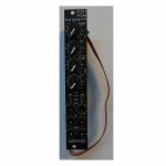
People also bought...
Doepfer A-130-2v VCAs Dual Linear/Exponential VCA Slim Line Series Vintage Edition Module (black) (dual/stereo/VCA synth module)
Cat: 973749 Rel: 14 Nov 23 • View all Synth modules
Dual linear/exponential VCA module - 4HP.
Notes: Module A-130-2v is composed of two identical voltage controlled amplifiers (VCA). Each VCA has a manual gain control (also named Initial Gain) and a control voltage input with attenuator. The character of the control scale can be switched to linear or exponential. All inputs and outputs are DC coupled. Consequently the VCAs can be used to process both audio and control voltages (e.g. for voltage control of the level of LFO or envelope signals). The signal input has no attenuator available but is capable to process up to 16Vpp signals (i.e. -8V...+8V) without distortion. For the processing of higher levels an external attenuator (e.g. A-183-1) is recommended.
The amplification range is 0...1. Even with a higher external control voltage the amplification remains at 1 (kind of "amplification clipping" at 1).
Controls (for each of both units):
Gain: manual gain control (Initial Gain) in the range 0...1
CV: attenuator for the CV input
lin/exp: switches the VCA characteristic to linear or exponential, in center position the VCA is off (mute function)
Inputs and outputs (for each of both units):
CV: control voltage input, min. +5V required for max. amplification (1) with CV control fully CW and Gain fully CCW
In: signal input, max. 16Vpp (+8V...-8V) without distortion
Out: signal output
A-130-2v is the slim version of module A-132-3 and offers essentially the same features. But the distances between the controls are smaller and rubberized small-sized knobs are used. In return the front panel has 4 HP only which is half the width of the A-132-3. The module is primarily planned for applications where only limited space is available.
Power consumption: 30mA at +12V and 30mA at -12V
Depth: 50mm
HP : 4
… Read moreThe amplification range is 0...1. Even with a higher external control voltage the amplification remains at 1 (kind of "amplification clipping" at 1).
Controls (for each of both units):
Gain: manual gain control (Initial Gain) in the range 0...1
CV: attenuator for the CV input
lin/exp: switches the VCA characteristic to linear or exponential, in center position the VCA is off (mute function)
Inputs and outputs (for each of both units):
CV: control voltage input, min. +5V required for max. amplification (1) with CV control fully CW and Gain fully CCW
In: signal input, max. 16Vpp (+8V...-8V) without distortion
Out: signal output
A-130-2v is the slim version of module A-132-3 and offers essentially the same features. But the distances between the controls are smaller and rubberized small-sized knobs are used. In return the front panel has 4 HP only which is half the width of the A-132-3. The module is primarily planned for applications where only limited space is available.
Power consumption: 30mA at +12V and 30mA at -12V
Depth: 50mm
HP : 4
2 in stock $93.69
Click for better price!
or call +44 20 7424 1960
quote 973749
quote 973749
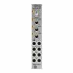
People also bought...
Doepfer A-147-5 Quad VCLFO Module (silver) (B-STOCK) (LFO synth module)
Cat: 991895 Rel: 01 Jan 90 • View all Synth modules
B-STOCK: Box opened, but product is in excellent condition and in perfect working order
Notes: ***B-STOCK: Box opened, but product is in excellent condition and in perfect working order***
Module A-147-5 contains four voltage controlled low frequency oscillators (VCLFO) with triangle waveform outputs. All LFOs share a common frequency control. Each of the LFOs 2, 3 features a Delta control which is used to shift the frequency of the LFO in question up or down. With the Delta controls at center positions the frequencies of all LFOs are roughly the same. To control the frequencies by external control voltages four CV inputs are available which follow roughly the 1V/oct standard.
The module has these controls and in/outputs available:
Control F: manual control of the frequency for all four LFOs
Control Delta F2, F3 and F4: manual control of the frequency shift up/down for the LFO in question
Sockets CV 1...4: Frequency control voltage inputs (normalled from top to bottom)
Sockets with triangle symbol 1...4: triangle outputs
LEDs: visual displays of the triangle outputs (red = positive, yellow = negative output voltage)
Application examples:
Generation of four triangle modulation signals with a common frequency control for all LFOs and individual controls for the frequency deviation of each LFO, manually adjustable and controllable by external control voltages
Generation of modulation signals for polyphonic FM/PWM applications. For this the four CV inputs are connected to the same control voltages which are used to control the frequencies of the corresponding VCOs. That way each LFO follows the frequency of the associated VCO with the possibility to control the frequency of all VCOs (control F) and the frequency deviations (Delta F controls). For the simultaneous modulation depth control the Quad VCA module A-130-4 is recommended.
Generation of complex modulation signals by summing up the outputs (e.g. by means of a mixer module A-138n / A-138i / A-138j)
Technical notes:
The level of the triangle outputs is about +/-5V (10Vpp)
The manually adjustable frequency ranges from about 0.025 Hz (about 40 seconds) to about 50 Hz with the delta controls of LFOs 2, 3 and 4 about center position
The frequency deviations adjusted by the delta controls are about +/-1:5. Example: with 1 Hz in center position the frequency shift ranges from about 0.2 Hz in position -5 to about 5 Hz in position +5 (1 Hz/5 = 0.2 Hz, 1 Hz*5 = 5 Hz).
The manual frequency controls and the control voltage inputs have an exponential control behavior
With external control voltage the max. frequency is about 150 Hz, the minimum frequency
The scale of the CV inputs is roughly 1V/oct (not adjustable)
The CV inputs are normalled from top to bottom. Provided that only socket CV1 is patched CV1 controls the frequencies of all four LFOs.
When each CV input is patched to it's own control voltage each LFO is controlled individually by it's own CV. In this case CV1 controls only the frequency of LFO1.
Internally the rectangle outputs are available at four terminals (typ level +/-10V or 20Vpp). If required they can be wired to four sockets of a DIY breakout module made by the user, 1k protection resistors are recommended to avoid short circuits. If lower levels are required passive attenuators (voltage dividers) may be used.
Internally is even an (unbufferd) triangle sum signal available. For this each of the four triangle outputs is simply connected to the sum output terminal via a 47k resistor. This output has high impedance and should be buffered or amplified to avoid level drop when the load changes (e.g. by means of an A-180-3 or A-180-4 or A-183-3).
By changing the values of the capacitors in the LFO circuits even other frequency ranges are possible (e.g. Quad VCO to form kind of a cloud VCO). Pay attention that the accuracy of the CV input scales is not sufficient for precise 1V/oct VCO applications. The 1V/Oct scales cannot be adjusted and the circuits are not temperature compensated.
Dimensions
4 HP
45 mm deep
… Read moreModule A-147-5 contains four voltage controlled low frequency oscillators (VCLFO) with triangle waveform outputs. All LFOs share a common frequency control. Each of the LFOs 2, 3 features a Delta control which is used to shift the frequency of the LFO in question up or down. With the Delta controls at center positions the frequencies of all LFOs are roughly the same. To control the frequencies by external control voltages four CV inputs are available which follow roughly the 1V/oct standard.
The module has these controls and in/outputs available:
Control F: manual control of the frequency for all four LFOs
Control Delta F2, F3 and F4: manual control of the frequency shift up/down for the LFO in question
Sockets CV 1...4: Frequency control voltage inputs (normalled from top to bottom)
Sockets with triangle symbol 1...4: triangle outputs
LEDs: visual displays of the triangle outputs (red = positive, yellow = negative output voltage)
Application examples:
Generation of four triangle modulation signals with a common frequency control for all LFOs and individual controls for the frequency deviation of each LFO, manually adjustable and controllable by external control voltages
Generation of modulation signals for polyphonic FM/PWM applications. For this the four CV inputs are connected to the same control voltages which are used to control the frequencies of the corresponding VCOs. That way each LFO follows the frequency of the associated VCO with the possibility to control the frequency of all VCOs (control F) and the frequency deviations (Delta F controls). For the simultaneous modulation depth control the Quad VCA module A-130-4 is recommended.
Generation of complex modulation signals by summing up the outputs (e.g. by means of a mixer module A-138n / A-138i / A-138j)
Technical notes:
The level of the triangle outputs is about +/-5V (10Vpp)
The manually adjustable frequency ranges from about 0.025 Hz (about 40 seconds) to about 50 Hz with the delta controls of LFOs 2, 3 and 4 about center position
The frequency deviations adjusted by the delta controls are about +/-1:5. Example: with 1 Hz in center position the frequency shift ranges from about 0.2 Hz in position -5 to about 5 Hz in position +5 (1 Hz/5 = 0.2 Hz, 1 Hz*5 = 5 Hz).
The manual frequency controls and the control voltage inputs have an exponential control behavior
With external control voltage the max. frequency is about 150 Hz, the minimum frequency
The scale of the CV inputs is roughly 1V/oct (not adjustable)
The CV inputs are normalled from top to bottom. Provided that only socket CV1 is patched CV1 controls the frequencies of all four LFOs.
When each CV input is patched to it's own control voltage each LFO is controlled individually by it's own CV. In this case CV1 controls only the frequency of LFO1.
Internally the rectangle outputs are available at four terminals (typ level +/-10V or 20Vpp). If required they can be wired to four sockets of a DIY breakout module made by the user, 1k protection resistors are recommended to avoid short circuits. If lower levels are required passive attenuators (voltage dividers) may be used.
Internally is even an (unbufferd) triangle sum signal available. For this each of the four triangle outputs is simply connected to the sum output terminal via a 47k resistor. This output has high impedance and should be buffered or amplified to avoid level drop when the load changes (e.g. by means of an A-180-3 or A-180-4 or A-183-3).
By changing the values of the capacitors in the LFO circuits even other frequency ranges are possible (e.g. Quad VCO to form kind of a cloud VCO). Pay attention that the accuracy of the CV input scales is not sufficient for precise 1V/oct VCO applications. The 1V/Oct scales cannot be adjusted and the circuits are not temperature compensated.
Dimensions
4 HP
45 mm deep
out of stock $92.21
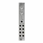
People also bought...
Doepfer A-130-4 Quad VCA Module (VCA synth module)
Cat: 973752 Rel: 14 Nov 23 • View all Synth modules
Quad VCA module - 4HP.
Notes: Module A-130-4 contains four linear VCAs with a common level control section for all four VCAs. It can be used for all applications of simultaneous amplitude/level control of up to four different audio or CV signals. A-130-4 is the replacement of the no longer available module A-132-2. Compared to the A-132-2 the width has been reduced from 8HP to 4HP.
The module has these controls and in/outputs available:
Control Man.: manual control of the amplification
Control CV: attenuator for the control voltage applied to socket CVo socket Input 1
Sockets In 1...4: VCA inputs 1...4
Sockets Out 1...4: VCA outputs 1...4
Application examples:
simultaneous amplitude/level control of up to four different audio or CV signals
polyphonic application 1: simultaneous control of the frequency modulation depth of 4 VCOs (Quad-LFO A-145-4 or Quad-VCLFO A-147-5 > A-130-4 > FM inputs A-111-4)
polyphonic application 2: simultaneous control of the pulsewidth modulation depth of 4 VCOs (Quad-LFO A-145-4 or Quad-VCLFO A-147-5 > A-130-4 > PWM inputs A-111-4)
simultaneous control of quadrophonic signals
Technical notes:
The maximum amplification for each VCA is about 1 ("Man." control fully CW). Even with an external control voltage applied to the CV input the maximum amplification is limited to 1.
The module is equipped with two internal connectors (pin headers with 4 pins each). Pin header #1 can be used to normalize the four inputs to other modules (e.g. Quad LFO A-145-4 or A-147-5, Quad ADSR A-143-2). Pin header #2 can be used to connect the four outputs to other modules.
The max. level at the VCA inputs without clipping/distortion is about 20Vpp or +/-10V.
Dimensions
4 HP
45 mm deep
… Read moreThe module has these controls and in/outputs available:
Control Man.: manual control of the amplification
Control CV: attenuator for the control voltage applied to socket CVo socket Input 1
Sockets In 1...4: VCA inputs 1...4
Sockets Out 1...4: VCA outputs 1...4
Application examples:
simultaneous amplitude/level control of up to four different audio or CV signals
polyphonic application 1: simultaneous control of the frequency modulation depth of 4 VCOs (Quad-LFO A-145-4 or Quad-VCLFO A-147-5 > A-130-4 > FM inputs A-111-4)
polyphonic application 2: simultaneous control of the pulsewidth modulation depth of 4 VCOs (Quad-LFO A-145-4 or Quad-VCLFO A-147-5 > A-130-4 > PWM inputs A-111-4)
simultaneous control of quadrophonic signals
Technical notes:
The maximum amplification for each VCA is about 1 ("Man." control fully CW). Even with an external control voltage applied to the CV input the maximum amplification is limited to 1.
The module is equipped with two internal connectors (pin headers with 4 pins each). Pin header #1 can be used to normalize the four inputs to other modules (e.g. Quad LFO A-145-4 or A-147-5, Quad ADSR A-143-2). Pin header #2 can be used to connect the four outputs to other modules.
The max. level at the VCA inputs without clipping/distortion is about 20Vpp or +/-10V.
Dimensions
4 HP
45 mm deep
1 in stock $79.27
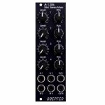
People also bought...
Doepfer A-138sv Mini Stereo Mixer Vintage Edition Module (black) (B-STOCK) (dual/stereo/mixer/panning/quad synth module)
Cat: 980376 Rel: 01 Jan 90 • View all Synth modules
B-STOCK: Item refurbished, repaired and in perfect working order.
Notes: ***B-STOCK: Item refurbished, repaired and in perfect working order.***
A-138s is a simple but useful 4-in-2 mixing tool. It has four inputs available. Each input is equipped with an attenuator (Level) and a panning control that is used to distribute the signal to the left and right output. Beyond stereo mixing it is equally suited to create variable parallel routings. For example: Any of the four inputs may be routed in variable intensity to feed two filters.
You may regard the A-138s as a smaller version of the A-138m Matrix Mixer.
Inputs and outputs are DC coupled, i.e. the module can be used for the mixing of control signals too.
- 3U Eurorack module, 8 HP wide, 30 mm in depth
- Power consumption: 10 mA at +12 V and 10 mA at -12 V
… Read moreA-138s is a simple but useful 4-in-2 mixing tool. It has four inputs available. Each input is equipped with an attenuator (Level) and a panning control that is used to distribute the signal to the left and right output. Beyond stereo mixing it is equally suited to create variable parallel routings. For example: Any of the four inputs may be routed in variable intensity to feed two filters.
You may regard the A-138s as a smaller version of the A-138m Matrix Mixer.
Inputs and outputs are DC coupled, i.e. the module can be used for the mixing of control signals too.
- 3U Eurorack module, 8 HP wide, 30 mm in depth
- Power consumption: 10 mA at +12 V and 10 mA at -12 V
1 in stock $77.08
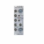
People also bought...
Doepfer A-196 PLL Phase Locked Loop Module (B-STOCK) (filter/oscillator/effect synth module)
Cat: 994989 Rel: 01 Jan 90 • View all Synth modules
B-STOCK: Box damaged, product in perfect working order
Notes: ***B-STOCK: Box damaged, product in perfect working order***
Module A-196 contains a so-called phase locked loop (PLL). The basic PLL system is shown in the sketch at the bottom of this page. A PLL consists of three parts: voltage-controlled oscillator (VCO), phase comparator (PC), and low-pass filter (LPF). All parts are normally connected to form a closed-loop frequency-feedback system.
This is how a PLL works: The output of the internal VCO (linear CV control, rectangle output) is compared with an external signal (e.g. the rectangle output of a A-110 VCO) in the so-called phase comparator (PC). The output of the phase comparator is a digital signal (low/high/tristate) that indicates if the frequency resp. phase difference of the two input signals is negative, zero or positive. The output of the phase comparator is processed by a low pass filter (LPF) to generate a smooth voltage that is used to control the frequency of the internal VCO. The 3 units VCO, PC and LPF form a feedback loop that works like this: The control voltage (output of the LPF) increases as long as the external frequency is higher than the frequency of the internal VCO und stops increasing when both frequencies become identical. The control voltage decreases as long as the external frequency is lower than the frequency of the internal VCO und stops decreasing when both frequencies become identical.
But there are some stumbling blocks: Different types of phase comparators with advantages and disadvantages can be made. Some phase comparators e.g. even lock at harmonics, i.e. if the two frequencies to be compared are integer multiples. But for some applications this can be used to create interesting effects. The A-196 contains 3 different types of phase comparators: PC1 is a simple exclusive OR, that even locks at harmonics. PC2 is a so-called RS flipflop and PC3 a more complex digital memory network. The user can select one of the three phase comparators with a 3-position switch. When PC2 is used a LED displays the "locked" state, i.e. when the frequency of the internal VCO is identical to the external frequency.
Special attention has to be directed to the frequency of the LPF. To obtain a smooth control voltage for the VCO the frequency of the LPF has to be much smaller than the lowest frequency of the internal or external audio signal. Otherwise the frequency of the internal VCO will jitter or wobble around the correct frequency. But for special effects this frequency jitter can be used intentionally. Example: frequencies in the range 50Hz...1kHz have to be processed with the PLL. Therefore the frequency of the LPF has to be about 10Hz or even less. Such a low frequency of the LPF causes a noticeable slew of the internal VCO. When the frequency of the external signal jumps e.g. between 500Hz and 1kHz it takes about 0.1 second until the internal VCO reaches the new frequency (like portamento). So one has to find a compromise between frequency jitter and portamento. But these remarks are valid only for the "ideal" working PLL. As the A-196 is used in a musical environment the "problems" and disadvantages with jitter and slew time lead to additional musical applications like portamento effects, wobbling frequencies or harmonic locking according to the type of frequency comparator and time constant of the PLL low pass filter. Instead of the internal manually controlled low pass filter the voltage controlled slew limiter A-171 can be used to obtain voltage control of this parameter. Normal audio filters (e.g. A-120, A-121) cannot be used for this job as the minimum frequency is to high (down to a few Hz or even less necessary) and the signal has to be DC coupled due to the low frequencies. Audio filters are normally AC coupled.
Another very important application of a PLL is frequency multiplication in combination with an external frequency divider. For this the output of the PLL-VCO is processed through an external frequency divider (e.g. A-163, A-160, A-161, A-115) before it is fed to In1 of the phase comparator. In this case the frequency of the PLL-VCO will be a multiple of the master frequency. E.g. if the A-163 is used and adjusted to dividing factor 5 the frequency of the PLL-VCO will be 5 times the frequency of the master VCO. Consequently, frequency division (A-163) leads to frequency multiplication with the PLL circuit. In combination with the PLL low pass frequency several effects can be realized (frequency multiplication with portamento or wobbling). The frequency multiplication can even be used to drive a graphic VCO. If your graphic VCO e.g. has 8 steps (e.g. A-155) and you use a frequency divider with factor 8 in the PLL feedback the output of the graphic VCO has the same frequency as the master VCO. Another application is the generation of pseudo-harmonics (not real harmonics as only rectangle waves are available) or clock generation for switched-capacitor filters.
… Read moreModule A-196 contains a so-called phase locked loop (PLL). The basic PLL system is shown in the sketch at the bottom of this page. A PLL consists of three parts: voltage-controlled oscillator (VCO), phase comparator (PC), and low-pass filter (LPF). All parts are normally connected to form a closed-loop frequency-feedback system.
This is how a PLL works: The output of the internal VCO (linear CV control, rectangle output) is compared with an external signal (e.g. the rectangle output of a A-110 VCO) in the so-called phase comparator (PC). The output of the phase comparator is a digital signal (low/high/tristate) that indicates if the frequency resp. phase difference of the two input signals is negative, zero or positive. The output of the phase comparator is processed by a low pass filter (LPF) to generate a smooth voltage that is used to control the frequency of the internal VCO. The 3 units VCO, PC and LPF form a feedback loop that works like this: The control voltage (output of the LPF) increases as long as the external frequency is higher than the frequency of the internal VCO und stops increasing when both frequencies become identical. The control voltage decreases as long as the external frequency is lower than the frequency of the internal VCO und stops decreasing when both frequencies become identical.
But there are some stumbling blocks: Different types of phase comparators with advantages and disadvantages can be made. Some phase comparators e.g. even lock at harmonics, i.e. if the two frequencies to be compared are integer multiples. But for some applications this can be used to create interesting effects. The A-196 contains 3 different types of phase comparators: PC1 is a simple exclusive OR, that even locks at harmonics. PC2 is a so-called RS flipflop and PC3 a more complex digital memory network. The user can select one of the three phase comparators with a 3-position switch. When PC2 is used a LED displays the "locked" state, i.e. when the frequency of the internal VCO is identical to the external frequency.
Special attention has to be directed to the frequency of the LPF. To obtain a smooth control voltage for the VCO the frequency of the LPF has to be much smaller than the lowest frequency of the internal or external audio signal. Otherwise the frequency of the internal VCO will jitter or wobble around the correct frequency. But for special effects this frequency jitter can be used intentionally. Example: frequencies in the range 50Hz...1kHz have to be processed with the PLL. Therefore the frequency of the LPF has to be about 10Hz or even less. Such a low frequency of the LPF causes a noticeable slew of the internal VCO. When the frequency of the external signal jumps e.g. between 500Hz and 1kHz it takes about 0.1 second until the internal VCO reaches the new frequency (like portamento). So one has to find a compromise between frequency jitter and portamento. But these remarks are valid only for the "ideal" working PLL. As the A-196 is used in a musical environment the "problems" and disadvantages with jitter and slew time lead to additional musical applications like portamento effects, wobbling frequencies or harmonic locking according to the type of frequency comparator and time constant of the PLL low pass filter. Instead of the internal manually controlled low pass filter the voltage controlled slew limiter A-171 can be used to obtain voltage control of this parameter. Normal audio filters (e.g. A-120, A-121) cannot be used for this job as the minimum frequency is to high (down to a few Hz or even less necessary) and the signal has to be DC coupled due to the low frequencies. Audio filters are normally AC coupled.
Another very important application of a PLL is frequency multiplication in combination with an external frequency divider. For this the output of the PLL-VCO is processed through an external frequency divider (e.g. A-163, A-160, A-161, A-115) before it is fed to In1 of the phase comparator. In this case the frequency of the PLL-VCO will be a multiple of the master frequency. E.g. if the A-163 is used and adjusted to dividing factor 5 the frequency of the PLL-VCO will be 5 times the frequency of the master VCO. Consequently, frequency division (A-163) leads to frequency multiplication with the PLL circuit. In combination with the PLL low pass frequency several effects can be realized (frequency multiplication with portamento or wobbling). The frequency multiplication can even be used to drive a graphic VCO. If your graphic VCO e.g. has 8 steps (e.g. A-155) and you use a frequency divider with factor 8 in the PLL feedback the output of the graphic VCO has the same frequency as the master VCO. Another application is the generation of pseudo-harmonics (not real harmonics as only rectangle waves are available) or clock generation for switched-capacitor filters.
out of stock $69.29

People also bought...
Doepfer A-140 ADSR Envelope Generator Module (silver) (B-STOCK) (envelope generator synth module)
Cat: 968709 Rel: 01 Jan 90 • View all Synth modules
B-STOCK: Box damaged, product in perfect working order
Notes: ***B-STOCK: Box damaged, product in perfect working order***
Module A-140 is an envelope generator, and, since it puts out control voltages, counts as one of the modulation devices in a modular system. As soon as the gate input receives sufficient voltage, the ADSR generates a variable voltage, changing in time, called an envelope. This varying voltage is output in normal (positive) and inverted form, and can be used, eg. for voltage controlled modulation of a VCO, VCF, or VCA, or for processing other modules' inputs and outputs.
The shape of the envelope is governed by four parameters: Attack, Decay, Sustain and Release.
The envelope is started (triggered) by a gate signal either from the INT.GATE voltage on the system bus, or, if a signal is put into it, from the gate input socket.
The envelope can also be re-triggered, i.e. start from scratch again, each time a trigger signal is sensed at the Retrig. input socket, when the gate is still open.
Module A-140 has available a three-position toggle switch to select one of three time ranges. The envelope duration ranges from about 50us (microseconds) up to several minutes.
In combination with the Comparator module A-167 a free-running "ADSR-LFO" can be realized.
… Read moreModule A-140 is an envelope generator, and, since it puts out control voltages, counts as one of the modulation devices in a modular system. As soon as the gate input receives sufficient voltage, the ADSR generates a variable voltage, changing in time, called an envelope. This varying voltage is output in normal (positive) and inverted form, and can be used, eg. for voltage controlled modulation of a VCO, VCF, or VCA, or for processing other modules' inputs and outputs.
The shape of the envelope is governed by four parameters: Attack, Decay, Sustain and Release.
The envelope is started (triggered) by a gate signal either from the INT.GATE voltage on the system bus, or, if a signal is put into it, from the gate input socket.
The envelope can also be re-triggered, i.e. start from scratch again, each time a trigger signal is sensed at the Retrig. input socket, when the gate is still open.
Module A-140 has available a three-position toggle switch to select one of three time ranges. The envelope duration ranges from about 50us (microseconds) up to several minutes.
In combination with the Comparator module A-167 a free-running "ADSR-LFO" can be realized.
out of stock $68.98
Items 1 to 18 of 18 on page 1 of 1
